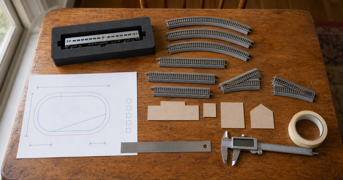
AI-generated illustration, not a scale drawing and not evidence of track geometry, wiring or clearance
Designing your own layout is the most enjoyable part of this hobby and the easiest one to get expensively wrong. The picture in your head — a train circling a small town, ducking through a tunnel, pulling into a platform — is lovely. What happens in practice is that a box of track arrives, gets assembled, and something does not work: the train will not take the curve, the platform is too short for the train, or one stretch of rail is permanently dead.
Almost all of that is avoidable by planning before purchasing. This is the sequence that does it.
Step one is not the table — it is what you want to run
| Field | What to write down |
|---|---|
| Vehicle baseline | Longest train, longest single car, where the powered unit sits, minimum radius, couplers, whether anything is lit, and whether anything has been modified. The most restrictive vehicle sets the geometry — never an average. |
| Operating tasks | Continuous running, two trains passing, holding one train while another goes by, reversing, switching, display or photography all want different track. Write three to five scenarios as "this train goes from here to there and stops at X". |
| Operators and control | One DC controller, two isolated sections, or DCC — this changes where gaps, feeders and turnout settings go. Define it now, not after the track is fixed down. |
| Permanent or temporary | Floor-laid, a table that packs away, a fixed baseboard and modules all have different needs for edge protection, cabling, access and transport. The outside dimensions of a table are not its usable area. |
If all you want is reliable continuous running, a manufacturer's basic set is a sound geometric starting point — KATO's M1 is built on R315 and lists its full contents, and TOMIX's pattern plans come from their own Basic Set and My Plan ranges. But a set is one specific solution, not a universal answer for every table, every fleet, or whatever you add next year.
Measure the clear space, not the length and width
- Usable clear length and width: subtract rounded corners, wall trunking, table legs, door swings, curtains and anything that cannot take weight.
- Edge and fall protection: the centerline cannot sit against the edge. You need roadbed width, the throw of the car ends, a margin for a derailment, and possibly a fascia.
- Clearance above: bridges, catenary masts, raised pantographs, cupboard doors and light fittings.
- Space below: turnout drives, feeders, connectors, cable runs, the controller and anything you need to unplug.
- Access for maintenance: can you reach the turnouts, inside the tunnels, the far track and the wiring without kneeling on the table or crushing scenery?
- The route out: if a fixed baseboard ever has to move, measure the doorway, the lift, the stair turn and where it will be stored.
Test "I can reach that" in the position you will actually be standing in, rather than assuming a generic arm's length. Put cardboard boxes where the buildings and hills will go, then rehearse cleaning the far track, lifting out a derailed train and swapping a turnout. If your body has to lean across the foreground, the answer is to narrow the layout, change to an L or U shape, split it into modules, or design a removable access hatch — not to promise yourself you will be careful.
Centerline radius is not baseboard radius
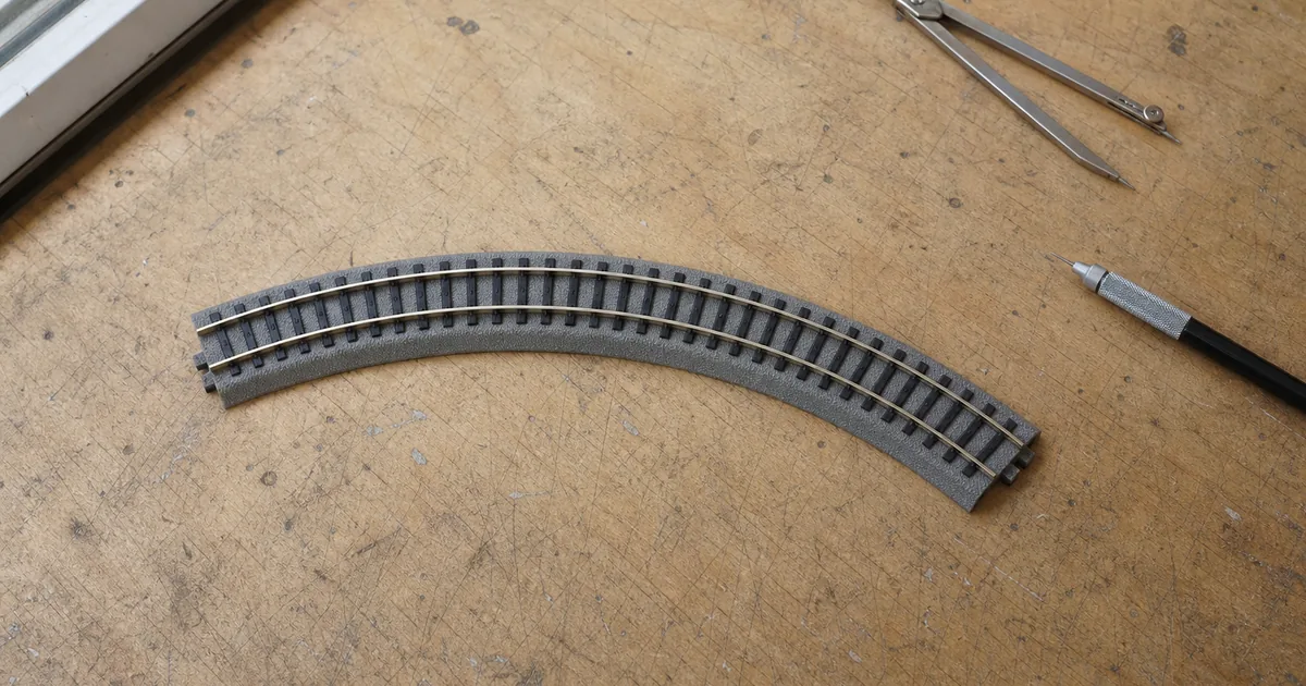
KATO labels curves R315-45 and R249-45; TOMIX labels them C280-45. The number after the letter describes that brand's curve geometry and should be read as the track centerline. It does not include the outer edge of the roadbed, the middle of a long car swinging toward the inside of the curve, the car ends throwing toward the outside, fall protection, or space for your fingers.
Conceptual, not to scale: a closed centerline is only the geometric starting point. Clearance on both sides has to be checked with your longest car.
For the narrow direction of an oval you can start from centerline diameter = 2 × radius, but only as a lower bound. Then add, item by item, the roadbed edge, the real swing of a real car, and a safety margin at the table edge. Compare candidate radii with the radius and board size guide, then confirm with a full-size paper template and your longest vehicle.
The longest train decides the platform, and the platform is not the siding
Start by establishing the longest train that will stop: add up the car lengths, or couple it up and measure it. Then keep two numbers apart, because conflating them is what produces a station a train does not fit in.
- Platform length: the physical stretch that serves passengers, driven by the train that stops there and by where the station building and ramps sit.
- Usable siding length: the stretch a train can stand in without fouling an adjacent route. Turnouts at both ends, clearance points, gaps, buffer stops and signals all eat into it.
- Passing loops: the longer train has to fit entirely inside before the main line is clear. Measuring the centerline between two turnouts overstates this every time.
- Terminal ends: allow stopping distance and a buffer beyond the length of the train. The edge of the table is not a valid stopping point.
Manufacturer parts lists keep turnouts, straights, platforms and gap pieces as separate line items for a reason — they are separate decisions. TOMIX publishes its own baselines, such as 37 mm standard double-track spacing and 55 mm for an island platform arrangement. Those figures apply to that system and those products; if you are mixing brands, or building a double-track section with a transition, you check it with the physical parts.
S-curves close on paper and fight each other in practice
A left curve running straight into a right one — or one turnout diverging directly into another the opposite way — loads adjacent cars and their couplers with opposite sideways displacements at the same time. Long cars, short couplers, fixed drawbars, propelled movements and reverse curves on a grade are all more sensitive to it.
- Mark every place on the plan where curvature reverses immediately, including a turnout diverging into a reverse curve.
- Insert a straight between them so the bogies and couplers of one full-length car have a chance to recenter. There is no fixed length that works for every fleet.
- Put two of your longest and least forgiving cars on a full-size paper template through the transition, and look at the angle between the car ends and the coupler.
- Once real track is temporarily laid, test with a full-length train at low speed, hauled and propelled, in both directions. One car at speed proves nothing.
If there is genuinely not enough space to remove the reverse loading, the correct decision may be to ease the curvature, use a different turnout, shorten the train or delete the branch — not to force the ends together and hope.
Grades: get the percentage first, then the transitions
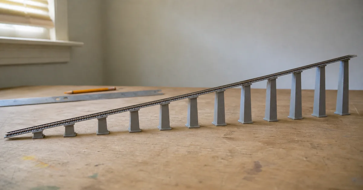
Grade percent = rise ÷ horizontal run × 100. Spreading the same rise over a longer run lowers the percentage — but curvature, train weight, wheel surfaces, where the powered unit sits and the couplers all change what a train will actually climb. A published figure such as TOMIX's 4% is a specification of their grade system, not a promise for every model, every train length and every curved ramp. Work out the numbers with the grade calculator before you commit to a height.
Four things get forgotten:
- Vertical transitions. A flat run meeting a ramp abruptly can foul the underframe, the pilot or the couplers of a long car at the top and bottom of the grade. Ease it progressively rather than folding a single sheet into an angle.
- Curved ramps add steering load on top of tractive load. Test with the full, heaviest train and its real power arrangement.
- Starting and stopping. Do not only test a high-speed climb. Confirm the train can start, stop and reverse slowly on the grade and near its foot.
- Turnout placement. Keep turnouts, uncouplers and rail joints away from an obvious vertical transition, and leave room for the drive and for cleaning.
A turnout is four decisions on one line of the bill of materials
| Record | What goes in the field | What happens if you skip it |
|---|---|---|
| Geometry | Brand, full SKU, hand, overall length, divergence, effective radius, included auxiliary track | The plan will not close, track centers drift, you accidentally create a reverse S-curve |
| Actuation | Manual or electric, drive unit, control switch, extension cables and terminals | You own the turnout and cannot throw it from where you stand |
| Power | Power routing or not, feed direction, gaps and feeders | A dead siding gets diagnosed as a fault, or two controllers feed back into each other |
| Vehicles | Longest car, wheel standards, couplers, hauled or propelled | One car passes, the full train picks the points or derails on the reverse curve |
| Maintenance | Point rail cleaning, drive replacement, plug access, holes underneath | The faulty turnout ends up under finished scenery |
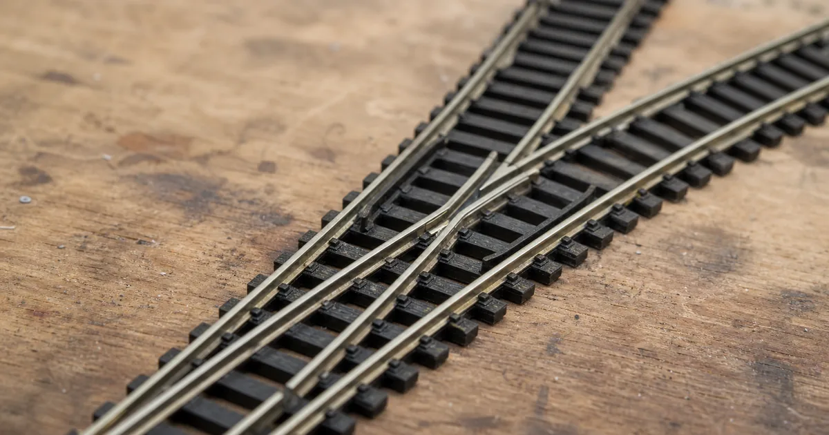
KATO's #4 (EP481) and #6 (EP718) differ in geometry, included parts and power-routing options — the comparison is in the #4 vs #6 guide. Do not choose from a left/right arrow on a screen.
The power-routing rules matter more than people expect, because they determine how passing loops, parking spots and multi-controller gaps behave. TOMIX describes fully-selective operation as feeding only the set route; KATO states that the #4 and the #2 wye can be set to power routing or not, while the #6 cannot. Draw the live path for every turnout position on paper before you buy.
Draw a second diagram: the one that shows power
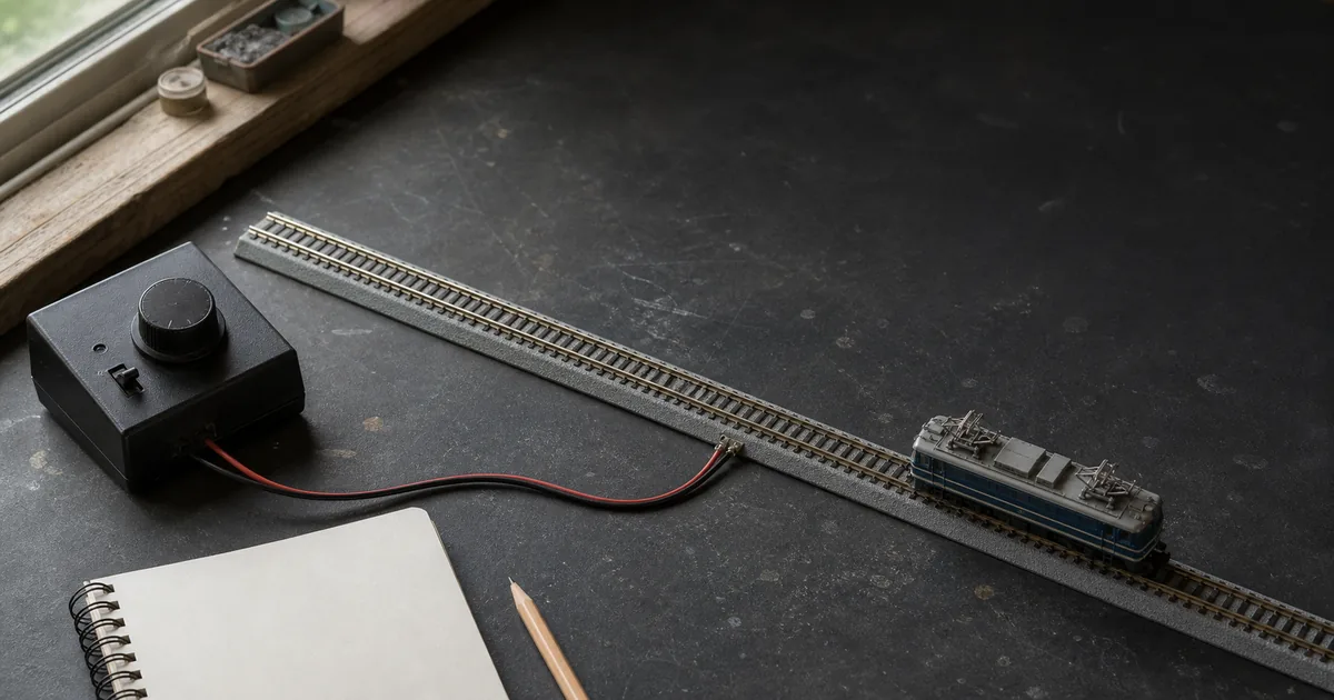
Your track plan shows geometry. It says nothing about which controller feeds which rail. A wiring diagram is a separate drawing, and it should mark at minimum:
- Every feeder, with its brand and SKU, its insertion direction and which controller it comes from.
- Every insulated joiner or gap, and the name of the section on each side of it.
- For each turnout, which branches are live in each position.
- The isolation boundaries for separate controllers, reverse loops, DCC or any automation.
- The far end of the run, anything under a bridge or inside a tunnel, and anywhere that will be hard to add wire to later.
Additional feeders on one continuous section must come from the same controller with matching polarity on both rails. How many feeders you need cannot be answered in feet — lay the track temporarily and compare positions with the same train, speed, direction and load, as described in the feeder and voltage drop guide. If the protection trips or a wire warms up after a change, cut the power immediately.
Both 9 mm gauge does not mean interchangeable geometry
KATO and TOMIX are both 9 mm N gauge, and for planning purposes that is where it ends. Straight modules, double-track spacing, roadbed thickness, joiners, feeder plugs, turnout control and power-routing logic all differ — KATO's system is built around a 248 mm straight, TOMIX's around 140 mm with an 18.5 mm roadbed width and 37 mm double-track centers.
Mixing should happen only at an interface you have confirmed, and a transition piece does not make the two geometry systems equivalent. Check the specific products, spacing, height, feeders and DCC boundaries against the KATO and TOMIX compatibility guide, and put the transition pieces on the bill of materials. Never take one brand's radius, divide it by some ratio, and substitute the other brand's part in software.
Six gates between a drawing and a shopping cart
- Requirements gate. Could the longest train, the operating tasks and the control method be satisfied by a simpler track arrangement? If yes, cut features before you go further.
- Table gate. Beyond the centerline, is there room for roadbed, body swing, edge protection, operation and maintenance? If not, enlarge the table or shrink the plan.
- Geometry gate. Minimum radius, S-curves, usable siding length, platforms, grades and turnout routes — each checked individually. If any fails, go back to the geometry draft.
- Electrical gate. Can feeders, gaps, turnout power and controller sections be explained on one separate diagram? If not, you are not ready to buy.
- Bill of materials gate. Does every line have a brand, a full SKU, a quantity, a purpose and a position? Including the things that are not track — control boxes, extension cables, piers, edge protection.
- Validation gate. Paper template and a temporary lay of the critical area first, tested with a full-length train. Buy only the stage you have proved.
Design-freeze certificate: what must be signed off
A plan is ready to freeze only when another person could reproduce the purchase and the acceptance test without relying on your memory. Give the freeze a revision ID and date, then close every record below. An unresolved exception means the plan is still a draft.
1. Revision identity
Plan ID, revision, date, owner and the operating brief this revision is intended to satisfy.
2. Governing train
Longest formation, most restrictive vehicle, powered-unit position, couplers and any modification that can change clearance.
3. Usable envelope
Measured clear surface, edge protection, operator position, maintenance reach and removable access for hidden track.
4. Geometry evidence
Centerline radii, turnouts, S-curve straights, grades, clearance points and usable platform or siding lengths.
5. Electrical drawing
Controllers, feeders, polarity, gaps, power-routing states, section names and the connector or extension part at each boundary.
6. Current bill of materials
Maker, full SKU, individual-piece count, package quantity, purpose and drawing position — with no generic “curve” or “wire” rows.
7. Validation evidence
Paper-fit result, temporary critical-area test and full-train runs in both directions, hauled and propelled, with failures recorded.
8. Exceptions and triggers
Named owner, next test and stop condition for every exception. No owner or evidence means no freeze.
Change trigger → gates to reopen
| If this changes after freeze | Reopen at least these gates | Why |
|---|---|---|
| Longest or most restrictive vehicle | Requirements, geometry, validation | Radius, overhang, coupler swing, grade and usable length may all change. |
| Controller, DC sections or DCC plan | Electrical, BOM, validation | Feeders, gaps, polarity, capacity and acceptance tests are no longer the approved configuration. |
| Turnout, sectional-track brand or transition | Geometry, electrical, BOM, validation | Roadbed, modules, power routing, controls and package counts differ even at the same 9 mm gauge. |
| Tunnel, scenery shell or table edge | Table, geometry, validation | Clearance, access and derailment recovery can fail without moving the centerline. |
Paper, then temporary track, then a full train
The three validation stages exist because each catches a different class of mistake:
- Full-size paper template on the real table. Catches "it does not fit", "I cannot reach the back corner" and "the door hits it". Costs nothing but a roll of paper.
- Temporary lay of real track over the critical area — the tightest curve, the S-curve, the ramp, the station throat. Catches geometry that closed in software but fouls in reality.
- A full-length train at low speed, both directions, hauled and propelled. Catches everything the first two cannot: coupler angles, overhang, pickup through turnouts, whether the powered unit can actually start the train on the grade.
This is the discipline the whole article is built on. A plan that closes in a track planner is a geometry result, not evidence that a train will run. Software cannot see your car's coupler swing, your particular locomotive's pulling ability, or the fact that your elbow does not bend that way. Use the track planner to get the geometry right and to produce a piece list — then prove it with paper and with trains.
If this feels like a lot, start smaller
Everything above scales down. If you are planning a first oval on a desk, most of the gates resolve in a sentence each: one train, one controller, one feeder, a radius your locomotive is rated for, and a table you have actually measured. The process is not bureaucracy — it is the same set of questions, and on a small layout they are quick to answer.
What the sequence really protects you from is the expensive version of the mistake: a large plan bought in one go, assembled, and then discovered to be unworkable. Buy in the order you validate. Prove the oval, then add the siding; prove the siding, then add the grade. For ideas sized to a shelf or a desk, see small-space layouts, and if you are considering building in sections instead, T-TRAK is a standardized way to do exactly that.
Railway-culture answer: Japanese floor layouts made reversibility a design virtue
KATO's official history says the company chose compact 9 mm gauge in 1963 with Japanese housing in mind, began mass-producing Japanese N-gauge models in 1965, and introduced UNITRACK in 1980 for stable layouts that could be assembled on a living-room or tatami floor and packed away. The planning lesson is current: build in reversible, testable stages, so a failed assumption costs one stage rather than a finished railway.
From a small room to a reversible railway
Open the note for the housing and product-design context behind temporary Japanese floor layouts.
Sources
Checked 2026-08-25. Planning method follows NMRA guidance; geometry, compatibility, turnout power routing and system baselines follow KATO's and TOMIX's own pages. A published example is not a current shopping list. For any specific product, the instruction sheet for that exact part number takes precedence over any article, including this one.
- NMRA: Beginner Layout Planning — goals and resources, iterative rough drafts, then a detailed scale drawing with dimensions, radii and grades
- KATO UNITRACK M1/M2 — R315 basic oval and listed set contents
- KATO UNITRACK Compact — R150/R183 vehicle restrictions and R249 fallback guidance when no minimum is stated
- KATO: Unitrack electric turnouts — geometry designations, included auxiliary track, power-routing options
- KATO Unitrack wiring accessories — feeders, terminal joiners, splitters
- TOMIX beginners page — system baselines for gauge, spacing and track modules
- TOMIX Super Mini and Mini Curve compatibility list — exact vehicles published for C103, C140 and C177 curves
- TOMIX support FAQ — 4% grade-system reference and selective point power behavior
- KATO USA UNITRACK plans — example-plan caveats about discontinued items, old prices and piece quantities
- KATO brand history — 1963 compact-gauge decision, 1965 mass production and 1980 UNITRACK floor-layout context
Get the geometry right, then prove it with trains
Track planning: common questions
What is the right order to plan an N scale layout?
Requirements, then table, then geometry, then power, then proof. Decide what you want to run and where it stops before you draw any track. Size the radius from the most demanding vehicle you own, measure the usable clear space rather than the outside of the table, lay out platforms, S-curves, grades and turnouts, draw a separate wiring diagram, and only then write a shopping list. Filling a table with track first is how people end up buying twice.
Is the R number on a curve the radius of the baseboard I need?
No. KATO's R315-45 and TOMIX's C280-45 describe the track centerline. That figure does not include the width of the roadbed, the overhang of a long car toward the inside of the curve, the throw of the car ends toward the outside, a margin so nothing falls off the edge, or room for your fingers. Centerline diameter equals twice the radius is a lower bound to start from, not the board width.
Can I treat R249 as a universal minimum radius?
No. KATO states that the R150 and R183 Compact curves suit only a limited range of stock, and TOMIX asks you to check the published list of vehicles that can negotiate C103, C140 and C177. If a particular model's instructions call for a larger radius, the model wins. Re-test after any coupler or body modification, because the modification may have changed what the vehicle will take.
How long does a platform need to be?
Start from the longest train that will actually stop there, either by adding up car lengths or by coupling the train and measuring it. Then remember that platform length is not the same as usable siding length: turnouts at each end, clearance points, gaps, buffer stops and signals all shorten the length a train can actually occupy. A terminus needs stopping and buffer room beyond the length of the train, so the table edge cannot be the end of the track.
Why does my train derail on an S-curve when each curve is fine on its own?
Because a left curve running straight into a right curve pushes adjacent cars and their couplers in opposite directions at the same time. Long cars, short couplers, fixed drawbars, propelling movements and reverse curves on a grade are all more sensitive. Insert a straight between the two curves so the bogies and couplers on your longest car have a chance to recenter, and test by hauling and propelling a full train slowly in both directions.
How do I calculate a grade?
Grade percent equals rise divided by horizontal run times 100, so spreading the same rise over a longer run lowers the percentage. But curvature, train weight, wheel surfaces, where the powered unit sits in the train and the couplers all change what a train can actually climb. TOMIX's published 4 percent is a specification of their grade system, not a guarantee that every model, every train length and every curved ramp will manage it.
What do I need to record about a turnout before buying it?
Four things, and they all belong on the same bill of materials. Geometry: brand, full SKU, hand, overall length, divergence, effective radius, included auxiliary track. Actuation: manual or electric, the drive unit, the control switch, extension cables and terminals. Power: power routing or not, feed direction, gaps and feeders. And vehicles: longest car, wheel standards, couplers, and whether the move is hauled or propelled. Skip the actuation row and you own a turnout you cannot throw from where you stand.
Why do I need a separate wiring diagram?
Because the track plan shows geometry and says nothing about which controller feeds which piece of rail. A wiring diagram records every feeder with its SKU and source controller, every insulated joiner and the sections either side of it, which branch of each turnout is live in each position, and the isolation boundaries for separate controllers, reverse loops or DCC. Draw it before you buy, not after the scenery is down.
Can I mix KATO and TOMIX track in one plan?
Both are 9 mm gauge, and that is where the similarity ends for planning purposes. Straight modules, double-track spacing, roadbed thickness, joiners, feeder plugs, turnout control and power-routing logic all differ. Mixing should only happen at a transition you have confirmed, and a transition piece does not make the two geometry systems equivalent. Never divide one brand's radius by some ratio and substitute the other brand's part.
How do I validate a plan before spending money?
In three stages. First a full-size paper template on the actual table, to check the shape fits the space and you can reach everything. Then a temporary lay of real track over the critical area — the tightest curve, the S-curve, the ramp, the station throat. Then a full-length train at low speed, in both directions, hauled and propelled. Buy only the stage you have proved. A plan that closes in software is a geometry result, not evidence that a train will run.
When is a track plan ready to freeze?
Freeze it only when the revision identifies the governing train, usable envelope, geometry and wiring drawings, exact current bill of materials and physical validation evidence. Every exception needs an owner and a next test. If the longest train, controller, track system, tunnel access or another governing assumption changes, reopen the affected gates before buying or fixing track.
Can I copy a published track plan and buy its parts list?
Use a published plan as a concept, not as a purchase order. KATO USA warns that example plans can contain discontinued items or old prices and that listed quantities are individual pieces rather than packages. Rebuild the bill of materials with current exact manufacturer SKUs, confirm package quantities, fit it to your usable space and validate the critical geometry with your own full train.