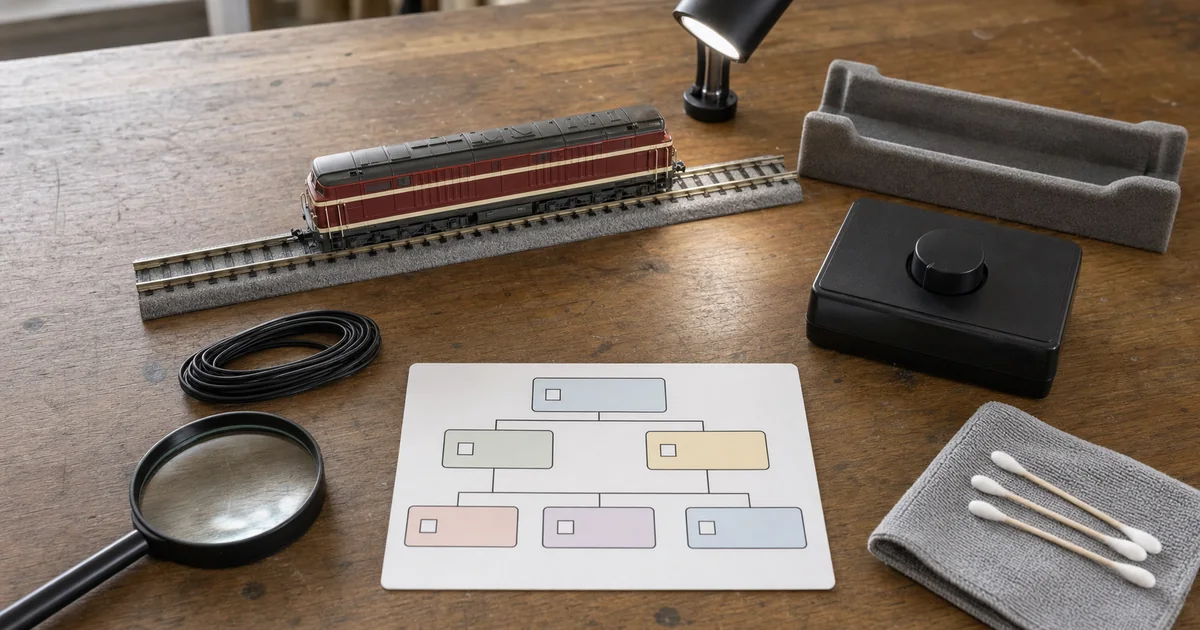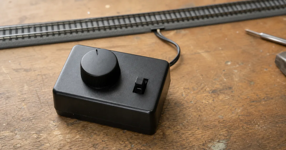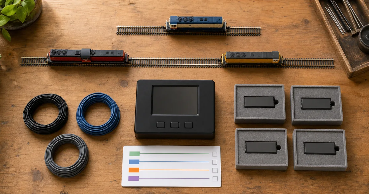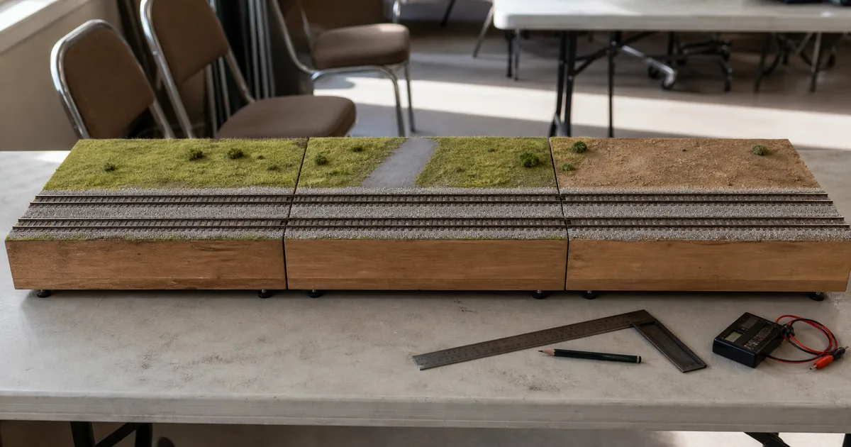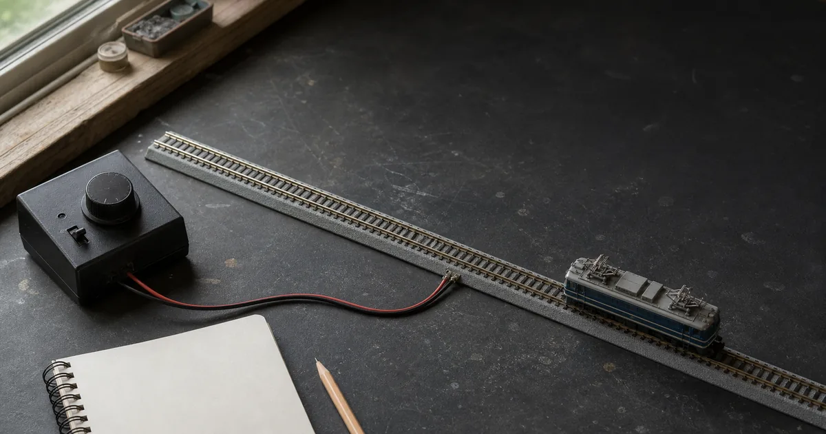
A train slowing at the far end does not, by itself, prove that you need another feeder. Rail and wire have resistance, so voltage loss is real; NMRA TN-9 says both run length and current matter, and that longer or more heavily loaded circuits lose more voltage. But the same symptom can come from wheel contact, a loose joiner, a power-routing turnout, a grade, a curve or an overloaded controller. The useful question is therefore not “How many feet between feeders?” It is “Which electrical path fails under a controlled load?”
Why a fixed feeder-spacing answer is incomplete
Search results often reduce the problem to a distance. That produces one memorable number but hides the variables that change the circuit. NMRA's beginner guide uses feeder drops spaced 2–3 feet apart in one bus-wiring example. TN-9 is more formal: it considers power-station rating, total out-and-back resistance, wire material and size, run length and maximum current, and recommends no more than 5% bus voltage loss at the farthest point under maximum current. These are different levels of guidance, not a universal promise for every product.
| Claim | What the source supports | ROKHELM use |
|---|---|---|
| Every N layout needs feeders every X feet | No universal manufacturer rule was found | HOLD until system and load are known |
| NMRA beginner 2–3 ft example | A practical bus-wiring illustration | Starting context, not a brand warranty |
| NMRA TN-9 5% recommendation | Bus performance at maximum current and farthest point | Design target for a documented system |
| KATO/TOMIX feeder accessories | Distribution of a documented output | A splitter is not a booster |
Six-step diagnosis before permanent wiring
1. Stop safely and map the electrical boundary
Set the throttle to zero and switch track power off. Mark every feeder, rail gap, turnout, crossover, reversing section and controller or booster boundary on the plan before changing any wire.
2. Build one repeatable operating test
Use the same known-good locomotive, direction, throttle command and load at the feeder area and at the suspect location. Record whether the controller trips, lights change or the vehicle slows.
3. Separate contact from supply
Clean rail and wheels by their maker's instructions, reseat joiners and feeder plugs, and repeat the unchanged test. A local improvement identifies contact resistance; no improvement keeps supply and routing hypotheses open.
4. Verify routing, load and polarity
Check the exact turnout manual, remove other trains and accessories, and confirm every feeder on one continuous section comes from the documented source with the same rail orientation. A trip, heat, odor or damaged wire is a STOP condition.
5. Measure with the correct method
For analogue DC, compare rail voltage under the same load using the voltage input and range documented for the meter. For DCC, use the command-station maker's specified method or suitable DCC instrument; do not treat a generic DC reading as DCC track voltage.
6. Make one documented change and retest
Choose one action—repair a joint, add a same-source feeder, resize a bus or create a protected district—then repeat the original test. Record the route, load, voltage or trip result before fixing scenery over the wiring.
Tool 1: symptom-to-evidence matrix
| Observed pattern | First hypotheses | Confirming comparison | Do not conclude yet |
|---|---|---|---|
| Every train changes at one location | Rail/joiner, routing, feeder path, geometry | Same direction/load before and after cleaning | The locomotive needs service |
| One train changes everywhere | Wheel/pickup, motor load, decoder or vehicle wiring | Known-good train on the same route | The layout needs more feeders |
| Only with more trains/lights | Controller capacity, wiring loss, short or accessory load | Add loads one at a time; record protection state | Distance is the cause |
| Only beyond a turnout | Power routing, internal isolation, gap, contact | Exact part manual and route position | The turnout is broken |
| Protection trips immediately | Reversed feeder, derailment, cross-boundary connection, short | Power off; do not repeatedly reset | A larger power pack will fix it |
The matrix narrows the strongest hypothesis; it does not prove one component. A locomotive can fail only on a particular frog or curve, and a weak joiner can appear acceptable until load rises. Keep conditions fixed long enough to see the interaction.
What KATO and TOMIX feeder parts actually do
KATO's accessory range includes feeder track, Terminal UniJoiner, extension cords and a three-way extension cord. TOMIX 5534 is a 70 cm D.C. Feeder N for basic single and double track, and 5812 is a branch cable for D.C. Feeder N. These are connection and distribution parts. They do not raise the source rating, create an independent throttle or certify arbitrary cross-brand wiring.
| Job | Appropriate interpretation | Boundary to verify |
|---|---|---|
| Add another point from one output | Documented splitter/branch and feeder | Total simultaneous load stays on that output |
| Run two lines independently | Independent outputs and independent lines | Gaps, turnouts and crossovers cannot join sources |
| Power an isolated special track | Follow the component instruction | KATO says its double crossover needs four approach feeders |
| Mix KATO and TOMIX wiring | HOLD unless an express interface is documented | Connector, source, polarity/phase and accessory circuit |
For controller ratings and regional adapters, use the KATO power-pack guide or TOMIX Power Unit guide. Compare DC and DCC before building districts around the wrong operating model.
Dead sidings, double track and special boundaries
A dead siding can be normal. A power-routing turnout may energize only the selected route, and an intentional gap may create a parking section. Before adding a feeder across it, identify the exact part and goal: should the track follow the turnout, remain switchable or stay live? The KATO #4/#6 guide and TOMIX point guide explain why part-number rules differ.
KATO's double-track guidance says independent trains require electrically independent tracks and independent outputs. Its double-crossover FAQ adds a part-specific exception: the crossing is internally isolated, so all four approach tracks require feeders. That is evidence for that component—not a rule that every ordinary rail section needs its own feed.
DC and DCC measurement are not the same job
For analogue DC, Fluke's general method gives the relevant boundary: black lead in COM, red lead in V/Ω, select DC voltage, and connect across the points being compared. On a model railway, keep the locomotive load and throttle command unchanged between locations. Avoid bridging the rails with a probe body, and never use a current input across the rails; that creates a short through the meter.
DCC is a bipolar digital waveform, not ordinary variable DC. A generic meter on its DC range is not a reliable DCC track-voltage instrument. Follow the command-station maker's test method and use a suitable meter or DCC-specific tool where required. NMRA TN-9 also links wiring to protection behavior: excessive resistance can prevent enough fault current from reaching a breaker. TN-9 describes a deliberate short-circuit trip test, but ROKHELM does not recommend a novice improvise it—use the manufacturer-approved procedure or qualified help.
Tool 2: power-path ledger and feeder Go/Hold/Stop gate
| Field | Record before wiring | Pass condition |
|---|---|---|
| Source | Controller/booster, adapter, output, protection rating | One documented source owns the section |
| Boundary | Both-rail gaps, turnout/crossover, reversing section | No hidden path to another output |
| Conductors | Material, bus/feeder size, out-and-back run, connectors | Matches manual, calculation and load |
| Load | Powered vehicles, lights, accessories, simultaneous use | Within output and breaker limits |
| Evidence | Location, direction, command, before/after result | Same test improves without a trip |
| Access | Label, connector, service opening, route on plan | Can be isolated after scenery |
- GO: source, boundary, conductor path, load and result are documented.
- HOLD: a part number, gap, source, rail orientation, phase or load is unknown.
- STOP: protection trips, wiring heats, insulation is damaged, smoke/odor appears, or two sources may meet.
Mark this ledger beside the layout plan and keep feeders reachable. The track planner helps reserve access; the troubleshooting guide gives the broader train-versus-location test. For modular boundaries, use the separate T-TRAK wiring guide.
Real railway power engineers also measure a system, not one distance
RTRI describes railway “feeding” as the complete circuit from traction substation through the contact-line system to the electric vehicle. Its Power Supply Systems laboratory studies voltage maintenance, fluctuation, short- and ground-fault detection, and simulations of substation current and minimum pantograph voltage with multiple trains. The equipment is entirely different, but the transferable modelling habit is sound: identify source, load, boundary, location and protection behavior before choosing a remedy.
Official and first-party sources
Checked 2026-08-15. Instructions for the exact controller, command station, turnout, crossover, feeder and meter override this guide. The two decision tools are ROKHELM editorial workflows, not manufacturer standards.
- NMRA TN-9 Wiring for DCC & DC — resistance, voltage loss, feeder sizing, protection and districts.
- NMRA Beginners Guide Part 5 — simple wiring, bus example, gaps and blocks.
- KATO UNITRACK wiring accessories — feeder and distribution parts.
- KATO: What is a power pack? — load, voltage drop, overload and wiring.
- KATO double-track power-pack guidance — independent outputs and isolation.
- KATO double crossover FAQ — internal isolation and four approach feeders.
- TOMIX 5534 D.C. Feeder N — supported track and 70 cm lead.
- TOMIX 5812 branch cable — D.C. Feeder N distribution.
- TOMIX official FAQ — power, turnout and controller boundaries.
- Fluke: measuring DC voltage — meter input and mode.
- RTRI Power Supply Systems laboratory — railway feeding, voltage and faults.
Diagnose the route before adding copper
N scale feeder wiring FAQ
How far apart should N scale feeders be?
There is no single spacing that is correct for every N scale layout. NMRA's beginner page gives 2–3 feet as one bus-wiring example, while the newer TN-9 sizes wiring from run length, current, resistance and voltage loss. KATO and TOMIX product pages define their feeder parts, not a universal interval. Use the maker's system instructions and prove the farthest point under the real load.
Does a train slowing far from the feeder prove voltage drop?
No. The location pattern makes voltage loss one hypothesis, but dirty wheel-to-rail contact, a weak joiner, turnout routing, grade, curve load or controller overload can produce a similar symptom. Repeat the same train, direction, throttle and load at both locations, then change one variable at a time.
Should a small N scale oval use a bus and many feeders?
Not automatically. NMRA says two wires from one power pack can be sufficient for a simple one-train layout. Add complexity only when the track plan, measured performance, current, joints, modules or operating districts justify it. Planning access for a future feeder is sensible; installing an unproved network is not required.
Does a splitter add current or power?
No. A KATO splitter or TOMIX branch cable distributes one documented output to more connection points. It does not increase the controller's rating. Add the simultaneous locomotive, lighting and accessory loads and keep them within the exact controller or power-station instructions.
Can I connect two DC controllers to one continuous section?
Do not connect two independent outputs directly to the same continuous rails. KATO's double-track guidance requires electrically independent lines for independent operation. Design gaps and selector logic from the exact system diagrams; if the boundary is uncertain, leave it unpowered and obtain qualified help.
Why is a siding or route beyond a turnout dead?
The turnout may be routing power only to the selected road, or the route may contain an intended electrical gap. Check the exact part number and its setting before bypassing it with a feeder. A new feeder can defeat a useful parking section or create a conflicting supply boundary.
Are DC and DCC feeder tests the same?
The isolation logic is similar, but the electrical measurements are not identical. Analogue DC varies rail voltage and polarity with the throttle; DCC places a bipolar digital signal on the rails. Use a DC-voltage method for DC and the command-station maker's specified method or a suitable DCC instrument for DCC.
Can I use a multimeter across N scale rails?
For analogue DC, use a correctly rated meter in its voltage mode, with leads in COM and V/ohm, and follow the meter manual. Never place a lead in a current input and then bridge the rails. For DCC, a generic DC reading is not a reliable track-voltage value; follow the DCC system maker's method.
What is a feeder decision gate?
It is a Go/Hold/Stop check before permanent wiring. GO means the electrical boundary, source, polarity or phase, load and test result are documented. HOLD means one of those facts is unknown. STOP means protection trips, wiring heats, insulation is damaged, odor or smoke appears, or two sources may meet.
When does an N scale layout need power districts?
Districts become useful when layout size, active vehicles, accessories, operators or fault containment justify separate protected areas. NMRA TN-9 treats this as a system-design decision, not a board-size formula. Follow the exact DCC or DC equipment manual and never improvise shared commons between incompatible outputs.
Does every track section need its own feeder?
No universal rule says it does. Some special components do have exact requirements: KATO says its double crossover is electrically isolated internally and requires feeders on all four approaches. Treat that as a part-specific instruction, not evidence that every ordinary rail section needs a feeder.
What should I record after a feeder fix?
Record the controller or booster, protection rating, bus and feeder material and size, route, gaps, turnout settings, active load, test location, direction, command and result. That ledger lets you reproduce the fix and prevents a later feeder from crossing an unseen district boundary.