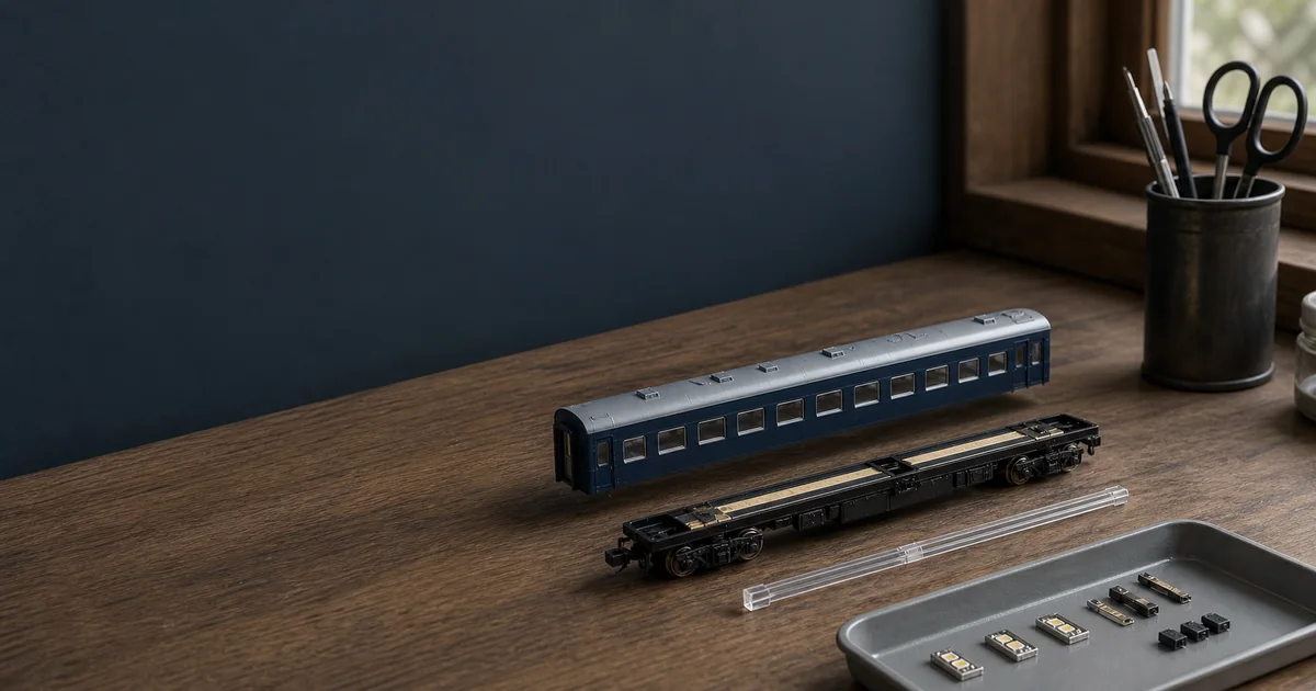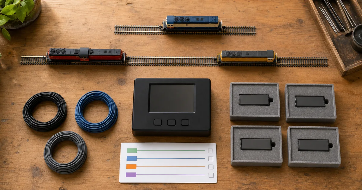
This guide assumes you have already decided that DCC solves a real operating need. If that decision is still open, use the DC vs DCC comparison first. The page you are reading answers the next search intent: how to get one N scale locomotive onto DCC without turning the first evening into an unsupported conversion experiment.
What the first DCC system actually needs
The NMRA beginner guide describes the core idea: a command station sends commands through powered rails and a decoder in each locomotive responds to its address. A practical beginner purchase is easier to audit by role than by package name, because some consoles integrate command station, booster and throttle while others divide those jobs differently.
| Role | What must be documented | Do not assume |
|---|---|---|
| Command station / throttle | Supported protocol, addressing and programming methods, user interface, firmware and manual | A phone app replaces the command station, or another maker's bus and handset will connect |
| Booster / track output | Approved supply, output, scale setting, protection and power-district instructions | A larger current rating repairs a short or poor feeder network |
| Feeder and test track | Wire connection, isolation arrangement and whether programming uses a dedicated output or the main output in another mode | Old DC wiring and rail joiners alone are automatically adequate for DCC |
| Mobile decoder | Exact interface or wiring, motor isolation, current rating, dimensions, functions and programming instructions | Any N-scale decoder fits any N-scale mechanism |
| Vehicle | Exact product number, maker DCC status, minimum radius, lighting arrangement and healthy baseline | A train name or body-shell photo proves the internal interface |
The NMRA's TN-9 adds an important corrective to the slogan that DCC needs only two wires. DCC places full signal voltage on the track when power is on, and a layout converted from DC may need changes for current capacity, voltage loss, feeders and protection. Use the feeder and voltage-drop guide when the test loop grows; addressing never substitutes for sound wiring or short-circuit protection.
Read the vehicle label as a boundary, not a promise
| Label or status | What it establishes | What remains to verify | First-locomotive status |
|---|---|---|---|
| Factory DCC / DCC Equipped | A decoder is installed | Decoder identity, address, function map, analogue mode and system requirements | PASS candidate |
| DCC Ready | A documented installation path may exist; the label does not mean a decoder is fitted | Exact socket or board, orientation, blanking plug, approved decoder, space, current and functions | HOLD until exact match |
| KATO DCC Friendly | Explicitly supported KATO vehicles accept designated Friendly decoders without soldering or modification | Which car and which motor, cab-light or interior-light decoder role the product page names | PASS only per documented car |
| Non-Friendly KATO | No Friendly drop-in path | KATO says wiring and soldering are required; decoder scale, purpose and other-maker support still need evidence | Specialist assessment |
| TOMIX | TOMIX's current FAQ says its products do not support DCC | An unofficial hard-wire project carries its own isolation, board, heat, space and support risks | Not a general beginner path |
“N scale” describes a scale-and-gauge family, not a decoder interface. Even within one trainset, the powered car, cab cars and intermediate lighted cars may need different parts or no supported part at all. The exact product page and instructions are the evidence; a successful conversion of a similar shell is only a research lead.
First-locomotive commissioning gate
This gate turns a vague “DCC compatible” claim into six decisions. The first three happen before power is applied; the last three prove that the system behaves safely.
1. Healthy baseline
PASS when the locomotive starts, reverses and traverses the intended route under the DC conditions its maker permits. Binding, pickup loss or abnormal heat is STOP.
2. Exact decoder path
PASS requires the exact vehicle number, decoder or interface, orientation, motor isolation, rating and function wiring. Brand, scale or train name alone is HOLD.
3. Test environment
Record the command station, approved supply, feeder, track output and programming method. DC and DCC supplies must never meet on the same rails.
4. Installation proof
Track power is off while fitting. No plug is forced, no board is cut without exact instructions, and every original part is retained.
5. Identity proof
Only the test decoder is exposed to service-mode commands. Record original values where the system can read them, choose a unique address and verify direction and basic functions.
6. Route proof
Low speed, stopping, both directions, functions, heat and the real route pass repeatedly. Smoke, odor, abnormal heat or repeated protection trips is STOP.
System completeness ledger: fill every cell before powering
Competitor guides often stop at “buy a starter system and a decoder.” This ledger catches the missing adapter, unsupported interface or programming assumption before it becomes a fault. Unknown is not failure; it is a reason to pause.
| Field | Record | PASS evidence | If unknown |
|---|---|---|---|
| Command station | Maker, model, firmware | Current manual and support page | HOLD |
| Power and output | Specified supply, scale/output setting, protection | System manual; no substituted supply | STOP |
| Programming method | Dedicated output, service mode on main output, or Operations Mode | Exact system procedure | HOLD |
| Vehicle | Maker, exact product and powered car | Box, product page and instruction agree | HOLD |
| Decoder | Maker, model, interface, current and functions | Vehicle and decoder documents match | STOP |
| Test track | Feeder, isolation and absence of other vehicles | Matches system manual; DC disconnected | STOP |
| Roster record | Factory state, assigned address, CV changes, function map | Written before the next locomotive is added | Create it now |
Programming track and Programming on Main are not the same
Service-mode programming is designed for testing and customising a decoder in a limited-energy environment, commonly with one decoder on an isolated section. Programming on Main, also called Operations Mode, addresses a selected decoder during layout operation. That distinction is useful, but the physical setup is not universal.
NCE's current Power Cab support page is a good example of why the exact manual matters. The Power Cab has one pair of track wires rather than a separate programming-track output; “Program Track Mode” changes how that same output behaves. NCE warns that program-track mode will program every locomotive on the connected rails, whereas Operations Mode begins by selecting an existing locomotive address. A different command station may have a dedicated programming output and a different workflow.
ROKHELM conservative rule: before first service-mode programming, remove every other locomotive and decoder-equipped vehicle from any rails connected to that output. Do not copy a menu sequence, reset CV or programming-track wiring from another system. Read-back availability, acknowledgement, reboot behavior and supported modes depend on the exact command station and decoder.
Six steps to commission the first locomotive
1. Choose one documented locomotive
Start with one healthy factory-equipped locomotive or one exact vehicle and decoder combination that the makers document. Record the product number, decoder, interface, current functions and system manual before opening anything.
2. Prove the locomotive before conversion
Run the unmodified locomotive under the DC conditions its maker permits. It must start, reverse and pass the intended route without binding, pickup faults or abnormal heat; a decoder cannot repair a mechanical or electrical baseline fault.
3. Build the smallest documented DCC test
Use the command station's specified power supply, one feeder and a short track arranged exactly as its manual requires. Keep every DC controller disconnected, remove other locomotives and confirm whether this system has a dedicated programming output or changes modes on the main output.
4. Install or verify with track power off
Disconnect track power before touching the vehicle or decoder. Follow the exact vehicle and decoder instructions for orientation, motor isolation, wires, lights and speaker; do not force a plug, cut a board or copy another model's wiring diagram.
5. Program one basic identity
Use the command station and decoder manuals to select the documented programming method. With only the test locomotive exposed to service-mode commands, read and record available defaults, set one non-conflicting address and test direction and basic functions before changing other CVs.
6. Prove operation before expanding
Test low-speed starts, both directions, stopping, each documented function and the real minimum-radius route. Stop for smoke, odor, abnormal heat, repeated protection trips or unstable behavior; add one locomotive or one setting only after the previous state passes.
The address roster is part of the railway
An address is useful only when the operator can identify it later. Record at least the vehicle product number, powered car, decoder, current address, function map, analogue-mode status if documented, important CV changes and the date of the last proven setup. Do not use a reset value from a generic forum post: reset procedures and supported address modes belong to the decoder manual.
Also keep one operational note: the direction that the model moves when the command station shows forward. If it is wrong, use only the decoder or vehicle maker's documented correction. Reversing motor wires may be appropriate in one hard-wire installation and completely wrong in a plug-in or board-replacement design.
Railway-culture answer: one train can contain several decoder jobs
A Japanese multiple-unit formation is not one locomotive-shaped electrical object. KATO's DCC Friendly system separates motor, cab-light and interior-light decoder roles, so different cars in the same train may need different designated parts. The modelling lesson resembles real multiple-unit practice: think in functional vehicles and formation boundaries, not only in a train name. This is a ROKHELM interpretation of KATO's product architecture, not a claim that every Japanese trainset uses the same decoder arrangement.
Do not assume a DC locomotive can wait on DCC track
Some systems implement an optional feature commonly called Address 00 or zero stretching for one conventional locomotive. It is not universal and it is not a safe migration plan. Digitrax documents Address 00 on applicable systems but warns that prolonged operation can cause heat buildup and eventual motor damage. NCE states that it does not support zero stretching and warns about heating, particularly with coreless or low-inductance motors.
The conservative first setup uses a decoder-equipped locomotive and keeps every unconverted vehicle off powered DCC rails unless the exact command-station and vehicle instructions explicitly allow otherwise. Never connect a DC controller and DCC output to the same rails at the same time. If a layout must switch supplies, the isolation and break-before-make arrangement must be documented for the exact equipment.
Official and first-party sources
Checked 2026-08-12. These sources establish standards, manufacturer support boundaries and system-specific examples; the ROKHELM gates and ledgers organise those facts into a conservative workflow. Exact current product manuals take precedence.
- NMRA beginner guide to Command Control and DCC — addressed decoders, system basics and beginner scope.
- NMRA Digital Command Control overview — current DCC overview and standards context.
- NMRA Standards and Recommended Practices index — current S-9 and decoder-interface status.
- NMRA DCC Service Mode conformance procedure — isolated, one-decoder and limited-energy programming environment.
- NMRA TN-9: Wiring for DC and DCC — track signal, feeders, current, voltage loss and protection.
- NMRA motive power and rolling stock guide — DCC Ready and factory-equipped terminology.
- KATO DCC Friendly FAQ — designated solderless motor, cab-light and interior-light decoder roles.
- KATO non-Friendly DCC conversion FAQ — wiring, soldering, decoder purpose and maker limits.
- TOMIX support FAQ — current statement that TOMIX products do not support DCC.
- Digitrax locomotive conversion guidance — start with a healthy motor and pickup system.
- NCE Power Cab programming modes — one output, service-mode scope and Operations Mode distinction.
- Digitrax Address 00 guidance — system-specific availability and motor-heating warning.
- NCE zero-stretching statement — unsupported feature and conventional-motor heating risk.
Make the decision before the installation
N scale DCC setup FAQ
What do I need for a first N scale DCC setup?
You need one documented DCC-equipped or supported decoder-ready locomotive, a command station with its specified power supply, one feeder, a short test track and the exact system and decoder manuals. Some consoles integrate command station, booster and throttle; others do not. List the functions rather than assuming every starter box contains the same architecture.
Should my first DCC locomotive be factory equipped?
Factory equipped is the lowest-complexity starting point when the exact decoder, address and function documentation is available. A maker-documented solderless installation can also be suitable. Do not make an unsupported motor-isolation and soldering project your first lesson in operating DCC.
Does DCC Ready mean a decoder is already installed?
No. DCC Ready generally indicates a documented installation path or interface, not an installed decoder. You still need the exact socket or board, orientation, space, approved decoder, current and function requirements. DCC Equipped or Factory DCC indicates an installed decoder, but its functions and analogue behavior still come from the exact instructions.
What is a DCC programming track?
Service-mode programming is intended for testing or customising one decoder in a limited-energy environment, commonly on an isolated section. The physical arrangement is system-specific: some command stations have a dedicated programming output, while an NCE Power Cab changes programming mode on its single track output. Follow the exact command-station manual and remove every other locomotive before service-mode programming.
Is Programming on Main the same as a programming track?
No. Programming on Main, often called Operations Mode, targets an addressed decoder during normal layout operation; service mode can act on any decoder exposed to the programming output and may support read-back depending on the system and decoder. The available commands and safeguards vary, so use the procedure documented by the exact command station and decoder.
What address should I use for my first DCC locomotive?
Use an address format supported by both the decoder and command station, then choose a number that is not already assigned in your roster. Record the factory state and the new address before writing it. Do not assume every decoder reset value, long-address procedure or read-back method is universal.
Does KATO DCC Friendly mean any decoder fits?
No. KATO says DCC Friendly applies only to vehicles explicitly identified for its designated Friendly decoders, installed without soldering or modification. Motor, cab-light and interior-light roles use different decoders, and KATO says those Friendly decoders cannot be used in non-KATO vehicles. Check every car and product number separately.
Does TOMIX officially support DCC conversion?
No. TOMIX's current official FAQ says TOMIX products do not support DCC. A third-party hard-wire conversion may be physically attempted by a specialist, but it must not be represented as TOMIX-approved, documented or warranty-safe.
Can I put a DC locomotive on DCC track?
Do not assume so. Address 00 or zero stretching is an optional system-specific feature, not a universal DCC capability. Digitrax documents it on applicable systems but warns that prolonged use can overheat and damage a conventional motor. Other makers, including NCE, do not support it. Use a decoder-equipped locomotive unless the exact system and vehicle instructions explicitly permit otherwise.
Can a decoder fix a locomotive that runs badly on DC?
No. Digitrax's conversion guidance says a decoder cannot compensate for a motor or pickup that does not work properly. Diagnose binding, dirty wheels, pickup loss, damaged gears and other baseline faults before conversion; otherwise DCC adds another variable without removing the original problem.
How many decoders can one Japanese trainset need?
Potentially more than one, because a formation can separate motor, cab-light and interior-light functions among different cars. KATO's DCC Friendly system explicitly lists different decoder roles. Build a per-car ledger from the exact train product page rather than buying one decoder for the train name.
When should I stop a DCC setup test?
Stop and disconnect power for smoke, odor, abnormal heat, repeated short protection, damaged wiring, a forced or reversed interface, or a locomotive that does not respond as its manual predicts. Also stop before installation when motor isolation, decoder rating, function wiring or the exact maker-supported path is unresolved.