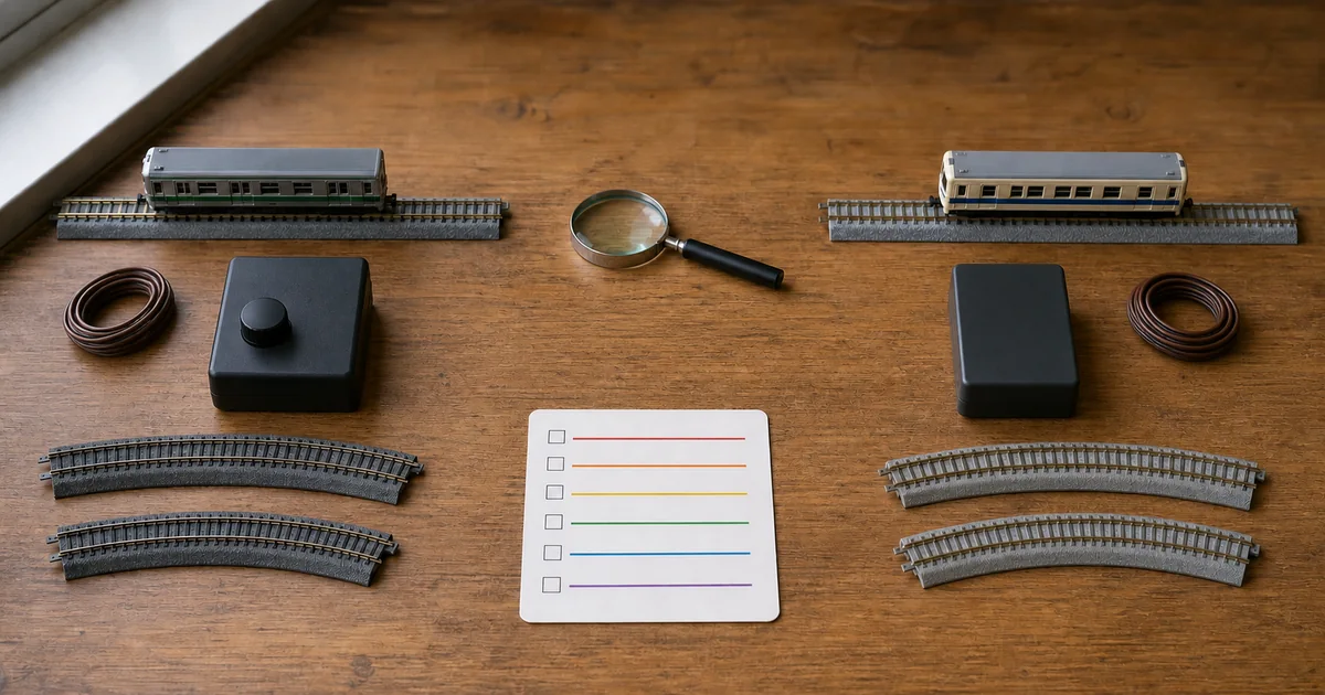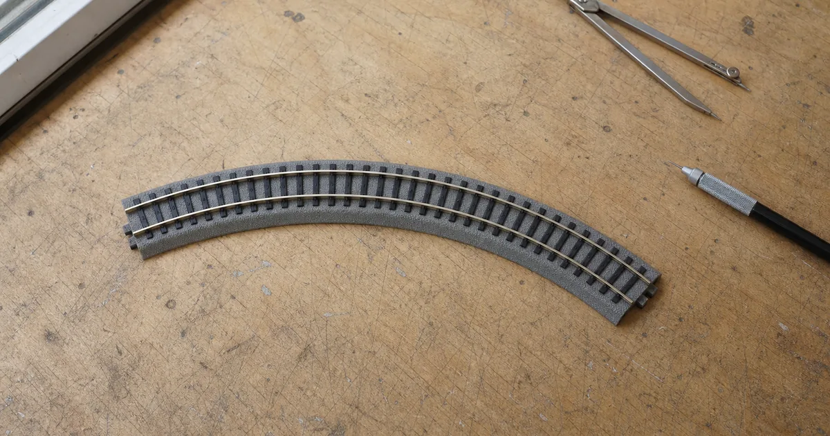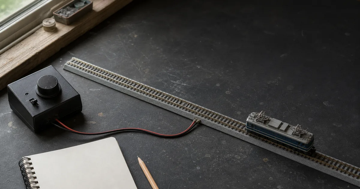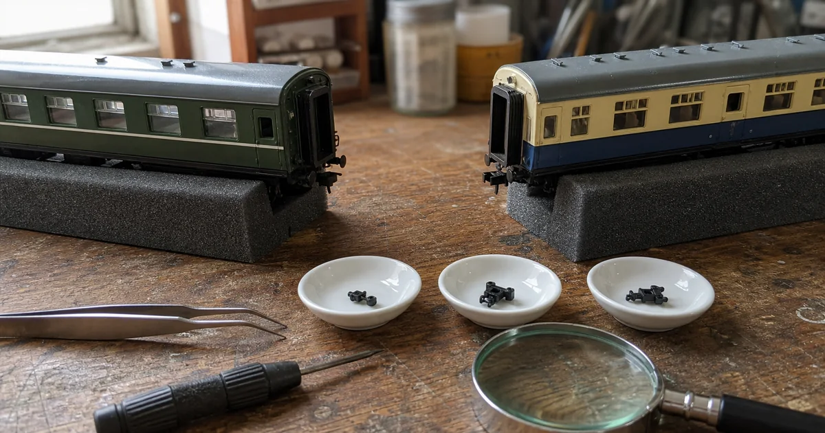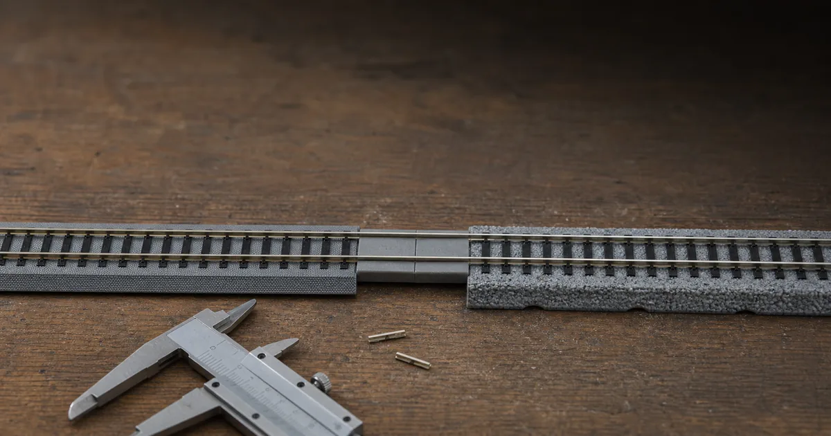
This guide is for a modeller who already owns both systems or has one specific reason to cross between them. If you are still choosing the main layout ecosystem, start with the broader KATO vs TOMIX comparison. Here the job is narrower: design one mixed-system boundary that can be inspected, powered and proven without calling every nearby interface “compatible.”
Compatibility is six different questions
Search results often collapse “the train ran across” into “the systems are interchangeable.” That shortcut misses the failures that appear only after a platform, second track, turnout motor, feeder or coupler is added. Use the following matrix before buying an adapter.
| Layer | What official evidence can establish | PASS | HOLD or STOP |
|---|---|---|---|
| Vehicle on rail | Both makers describe broad cross-brand N-gauge running. | PASS | Exact radius, clearance, voltage or die-cast/display exception unresolved. |
| Physical joint | 20-045, 1529 or 1530 provides a documented transition route. | PASS | Native joiners forced together; special track profile assumed to fit. |
| Planning grid | UNITRACK publishes 248 mm/33 mm; FineTrack publishes 140 mm/37 mm. | HOLD | Parallel roads expected to line up without a deliberate spacing transition. |
| Power path | A controller may operate another maker's conventional DC vehicle within limits. | HOLD | Plug, feeder, turnout or supply compatibility inferred without exact documentation. |
| Magnetic track | KATO documents a slotless-motor interaction risk and possible mitigations. | HOLD | Magnetic turnout or uncoupler behavior not tested with the actual vehicle. |
| Train functions | Coupler, light and DCC claims belong to each vehicle and part. | SEPARATE | Track compatibility used as evidence for couplers, lighting or decoder support. |
Decision rule: pass the vehicle and joint layers before construction, then resolve the geometry, power and magnetic layers at the real boundary. Treat train functions as separate projects. A green result in one row never carries into the next.
Choose one adapter path
| Product | Documented role | Use boundary | Do not infer |
|---|---|---|---|
| KATO 20-045 | 62 mm Joint Track for UNITRACK to fixed track or another maker's roadbed track 19 mm wide or narrower. | A straight transition led from the UNITRACK side. | That every FineTrack special profile is within the condition. |
| TOMIX 1529 | 35 mm S35-J joint track; change the joiner as the product directs. | A straight transition with wood-tie appearance. | That it is uniquely “the KATO adapter.” |
| TOMIX 1530 | 35 mm S35-J-PC joint track; same transition role with PC-tie styling. | A straight transition with concrete-tie appearance. | That 1529 and 1530 must be combined. |
Choose the product whose documented installation is clearest for the boundary you can keep accessible. Do not stack both makers' adapter pieces to appear “more compatible.” Every extra joint adds another alignment and electrical contact to inspect.
KATO's 19 mm condition explains why 20-045 is relevant to standard FineTrack, whose published basic roadbed width is 18.5 mm. It does not automatically approve Wide, Slab, Tram, turnout or embedded-track variants. If the exact profile is not named or dimensionally documented, mark it HOLD and dry-fit the actual pieces before designing scenery around them.
An adapter changes the joint, not the grid
KATO publishes a 248 mm basic straight and 33 mm standard double-track centres. TOMIX publishes a 140 mm basic straight, 18.5 mm basic roadbed width and 37 mm centres. The track-centre difference is 4 mm. That is enough to prevent two parallel routes from continuing as one unchanged pair.
Length also needs deliberate closure. Do not expect a 248 mm module and a 140 mm module to repeat into the same endpoint. Use each maker's documented adjustment pieces on its own side and verify the final joint on the board. The track planner can compare libraries, but a digital centreline cannot certify rail-top height or roadbed rocking.
Vehicle-level power is not wiring-system compatibility
TOMIX says its controller can operate another maker's conventional vehicle and vice versa. KATO likewise advises matching its power pack to its track while describing broad other-brand vehicle operation. The safe conclusion is narrow: vehicle-level analogue operation may cross brands within the documented limits; plugs, feeder leads, turnout controls, accessory outputs and AC adapters do not become interchangeable.
Respect the vehicle's voltage limit, not the maximum position of an unfamiliar throttle. TOMIX warns that operating a TOMIX vehicle above DC 12 V can damage the motor or circuit board and may cause heat or fire. Stop immediately for abnormal heat, odor, smoke, arcing or repeated protection trips. For larger layouts, diagnose the existing path before adding feeders; the feeder and voltage-drop guide separates dirty rail, loose joints and real distribution loss.
The slotless-motor exception deserves its own test
KATO warns that magnetism from a slotless motor may affect another maker's magnetically operated turnout or uncoupler track. This is an interaction problem: the vehicle may run perfectly on plain rail and still mis-operate one component. A successful straight-track test therefore cannot clear the whole route.
Run each slotless-motor vehicle slowly over every magnetic component in both directions before fixing the boundary or buying a fleet quantity. If a problem appears, stop and consult KATO's demagnetising-plate and magnetising-sheet guidance. KATO says those aids may improve the problem; it does not promise a cure. Record the exact vehicle, component, direction and result instead of generalising from the brand name.
Six steps to build and prove one boundary
1. Choose one accessible boundary
Place the transition on a flat straight where both sides, the joiners and the underside wiring remain reachable. Do not bury the first mixed-system joint in a tunnel, turnout ladder, curve or permanent scenery.
2. Select one official joint-track path
Use KATO 20-045 or one TOMIX S35-J route, 1529 for wood-tie styling or 1530 for PC-tie styling, according to the current product instructions. Do not stack both makers' adapters or force their native joiners together.
3. Preserve each system's grid
Treat the adapter as one rail boundary, not a geometry converter. Keep UNITRACK's 248 mm and 33 mm planning grid on its side and FineTrack's 140 mm and 37 mm grid on its side; transition only after the parallel tracks have become one straight route.
4. Build and inspect unpowered
With track power disconnected, dry-fit the boundary on a rigid flat base. Check both rail tops and inner rail faces for a vertical step, lateral kink, loose joiner or roadbed rocking, then hand-roll representative unpowered stock in both directions.
5. Power from one documented control path
Feed the continuous test route from one controller and the feeder system documented for it. Keep every other controller disconnected, verify polarity before adding feeders, and stay within the exact vehicle and controller instructions rather than treating plug shape as electrical approval.
6. Prove representative vehicles before scenery
Run the longest car, longest rigid-wheelbase vehicle and any KATO slotless-motor vehicle slowly in both directions, then test nearby turnouts and uncouplers. Stop for a step, wheel climb, short, heat, protection trip or magnetic mis-operation; fix and repeat before securing or hiding the boundary.
Make the boundary replaceable
A reliable transition is not necessarily permanent. Leave enough straight track on each side to release the joiner without tearing scenery, label the underside feeder path, photograph the rail alignment before covering nearby ground, and keep the product instructions with the layout record. These are ROKHELM maintenance recommendations, not manufacturer requirements.
Also preserve a known-good test vehicle for each demanding category: longest car, longest rigid wheelbase, smallest pickup footprint and slotless motor if present. When a later fault appears, repeat the same direction and low speed before cleaning or dismantling. That makes the boundary diagnosable instead of merely hidden.
Railway-culture answer: modular railways standardise the edge
NRail's current T-TRAK standard illustrates the engineering principle behind a dependable boundary. It requires KATO UNITRACK at module ends and fixes the two mainline tracks at 33 mm centres, while leaving sidings, yards and much of the module scene to the modeller. The lesson is not that every layout should use T-TRAK; it is that independently built railway sections can meet when the edge geometry and wiring convention are explicit.
Official and first-party sources
Checked 2026-08-12. Product pages establish the adapter and geometry claims; support pages establish cross-brand, voltage and slotless-motor boundaries. The compatibility matrix and acceptance gate organise those facts conservatively. Exact current product instructions take precedence.
- KATO: What is UNITRACK? — two-rail 12 V scope, 248 mm grid, 33 mm centres and replaceable UniJoiner.
- KATO straight-track range — 20-045 as a 62 mm Joint Track for other roadbed up to 19 mm wide.
- KATO FAQ: connecting another maker's track — official joint-track route.
- TOMIX FineTrack introduction — 140 mm base length, 18.5 mm roadbed width and 37 mm centres.
- TOMIX 1529 product page — S35-J wood-tie joint track.
- TOMIX 1530 product page — S35-J-PC joint track.
- TOMIX support FAQ — other-brand running, controller, voltage, coupler and DCC boundaries.
- KATO slotless-motor FAQ — possible effects on another maker's magnetic turnout or uncoupler.
- KATO magnetic countermeasure FAQ — demagnetising plate and magnetising sheet limits.
- KATO power-pack FAQ — same-maker track/power guidance and other-brand vehicle scope.
- NRail T-TRAK standard — KATO UNITRACK at module ends, 33 mm centres and module-versus-layout wiring distinction.
Plan the boundary before buying it
KATO and TOMIX track compatibility FAQ
Can TOMIX trains run on KATO UNITRACK?
Most conventional two-rail 9 mm DC N-gauge vehicles can normally run on UNITRACK, subject to the exact vehicle's minimum radius, clearance and voltage limits. KATO describes UNITRACK as a two-rail 12 V system for N-gauge stock, but a successful rail fit does not certify couplers, lighting parts, DCC support or every magnetic track component.
Can KATO trains run on TOMIX FineTrack?
Usually, but not as a blanket promise. TOMIX says other makers' N-gauge vehicles can run on FineTrack while noting limited exceptions. Check the exact vehicle's radius and clearance, and separately test any KATO slotless-motor vehicle around magnetic turnouts or uncoupler tracks.
Can UNITRACK and FineTrack connect directly?
Not by clipping their native joints together. Use one documented joint-track path: KATO 20-045, or TOMIX 1529 or 1530 with the joiner procedure supplied for that product. Do not force the standard joiners or treat a physical connection as proof of electrical and geometric compatibility.
What is KATO 20-045?
KATO 20-045 is a 62 mm Joint Track. KATO specifies it for connecting UNITRACK to fixed track or another maker's roadbed track with roadbed 19 mm wide or narrower. That condition does not automatically approve every FineTrack variant, turnout, slab, tram or wide-track profile.
What is the difference between TOMIX 1529 and 1530?
Both are 35 mm S35-J joint tracks intended to connect another maker's rail after the joiner is changed as instructed. TOMIX 1529 has wood-tie styling; 1530 has PC-tie styling. They are appearance alternatives, not two halves that must be used together.
Do I need both a KATO adapter and a TOMIX adapter?
No. Select one official joint-track path and follow that product's instructions. Stacking two adapter products creates extra joints without making the two planning grids, feeders or control accessories interchangeable.
Do KATO 33 mm and TOMIX 37 mm track centres line up?
No. The published standard centres differ by 4 mm. An adapter joins one rail boundary; it does not turn a 33 mm pair into a 37 mm pair. Reduce the route to one straight track before the boundary, then build each side with its own geometry.
Are KATO and TOMIX feeders or controllers interchangeable?
Do not infer wiring compatibility from cross-brand vehicle operation. Keep feeder, turnout-control, accessory and AC-adapter connections within one documented system unless an exact maker-specified interface says otherwise. A continuous test route should have one documented control path, with any added feeders sourced from that same path and checked for polarity.
Can a KATO slotless-motor train affect a TOMIX turnout?
It can affect a magnetically operated component. KATO warns that slotless-motor magnetism may influence another maker's magnetic turnout or uncoupler track. Test every such boundary at low speed. KATO's demagnetising plate or magnetising sheet may improve a problem, but KATO does not guarantee a cure.
Does track compatibility mean coupler compatibility?
No. Rail gauge, track joints and couplers are separate interfaces. TOMIX says cross-brand coupling is generally unsupported except for some freight cars and says TN couplers are not compatible with other brands. Verify the exact car ends and coupler parts independently.
Can I mix track in a hidden section?
A mixed boundary can work in hidden track, but the first and most service-critical joint should remain accessible. Prove the transition on a flat straight before hiding it, and retain access for rail cleaning, joiner inspection, wiring checks and replacement. This is a ROKHELM maintenance rule, not a manufacturer requirement.
What should I test before fixing the adapter into scenery?
With power off, inspect rail-top height, inner-face alignment, joiner engagement and roadbed stability, then hand-roll representative stock both ways. Power the route from one documented path and test the longest car, longest rigid-wheelbase vehicle and any slotless-motor vehicle at low speed. Do not hide the boundary until there is no wheel climb, short, heat, protection trip or magnetic mis-operation.