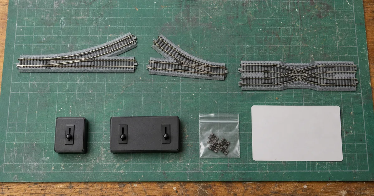
Scope: current TOMIX FineTrack standard electric PR/PL541-15 and PR/PL280-30 points, plus the related drive, control and PX280 boundaries cited below. Instructions packed with the exact product override this guide.
TOMIX names carry useful geometry, but the code is not a complete plan. A correct turnout choice also needs the companion curves, resulting track centres, power-routing map and a test with the trains that will actually use it.
Decode the name without guessing
| Code | Verified meaning in this guide | Do not infer |
|---|---|---|
| PR / PL | Right / left branch from the single-track approach on the cited products | Hand from a rotated product photograph |
| 541-15 | R541 diverging geometry, 15° | A universal minimum radius for every vehicle |
| 280-30 | R280 diverging geometry, 30° | That the entire formation fits in 140 mm |
| F | FineTrack family | Compatibility with every feeder, controller or other-brand joint |
| Fully selective | Power follows the selected mechanical route | No need to plan feeders, gaps or reversing boundaries |
541 versus 280: verified geometry
| Field | PR/PL541-15 | PR/PL280-30 |
|---|---|---|
| Current electric right/left items | 1271 / 1272 | 1273 / 1274 |
| Body length | 140 mm | 140 mm |
| Diverging curve | R541, 15° | R280, 30° |
| Companion geometry | With C541-15 | With two C280-15 |
| Published resulting centres | 37 mm | 74 mm |
| Two-point crossover | 37 mm centres over 280 mm | 74 mm centres over 280 mm |
The body-length match is useful for sectional planning, but it does not make the routes interchangeable. The diverging angle and companion pieces change the exit position. Compare this with the adjacent KATO #4/#6 guide, but do not transfer one maker's geometry into the other.
Tool 1: exact-point geometry ledger
| Record | PASS evidence | HOLD |
|---|---|---|
| Product | Current item number, PR/PL and instructions | Only a photo or “TOMIX point” known |
| Geometry | Body, radius, angle and companion pieces drawn | Only body length fits |
| Centres | 37 or 74 mm result matches the plan | Parallel road or platform assumed |
| Vehicle | Exact required trains selected for test | “N scale” used as a clearance guarantee |
| Electrical | Selected routes, feeders and gaps mapped | Fully selective treated as automatic wiring |
| Service | Drive and point blades remain reachable | Scenery seals the mechanism |
Fully selective power is a behavior, not a wiring plan
TOMIX defines fully selective operation as feeding only the route selected by the point. The PR/PL541 and PR/PL280 product pages describe both rails changing through internal contacts. This can simplify some arrangements, but a feeder on another part of the layout can energise a route from the far side. Reversing sections and independent blocks still need an explicit electrical plan.
Power off before changing wiring or joiners. Mark every feeder and gap, then test both point positions. TOMIX says gaps can be created with separately sold insulated joiners; install them only where the documented plan calls for isolation. For the wider system, use the feeder guide.
Manual, electric and double-crossover boundaries
TOMIX's FAQ says a manual FineTrack point can be made electric with drive unit 0107. The unit uses a connector and can slide out from the side after track is fixed, which is a strong reason to leave side access. Control box N-S switches one electric point; N-W switches two simultaneously. Match the point, control box and documented power source rather than forcing an unfamiliar connector.
PX280 item 1247 is a 280 mm double crossover and uses two point drive units. Its product page specifies the Next Neo control system. Treat it as a dedicated product with its own manual—not as proof that any two ordinary points can be wired the same way.
Tool 2: one-point acceptance gate
| Test | Observe | PASS |
|---|---|---|
| Throw cycle | Both positions, repeated | Blades seat fully every time |
| Route power | Motor/lights at low speed | Selected route powered as planned |
| Wheel passage | Actual demanding vehicles | No repeated climb, bind or derailment |
| Direction | Both directions; hauled/propelled if used | Every required move succeeds |
| Access | Drive side and rail joints | Service remains possible after scenery |
Run the same conditions before and after reconnecting adjacent track. If a symptom repeats only with one train at one route, keep the interaction hypothesis open; the point or the train does not automatically become the sole cause. The troubleshooting matrix shows how to isolate that case.
Six-step workflow
1. Record the exact point and route
Write down the product number, PR or PL hand, intended route, normal direction and every train that must use it.
2. Decode radius, angle and body length
Read 541-15 or 280-30 as published geometry, then confirm the exact current product page instead of identifying the point from a photograph.
3. Draw companion pieces and track centres
Draw the turnout with its matching curves, approaches and parallel tracks; verify whether the formation produces 37 mm or 74 mm centres.
4. Map fully selective power and gaps
Mark the selected and unselected routes in both positions, plus every feeder, insulated joiner, reversing boundary and control connection.
5. Dry-lay and test every required move
Before fixing track, run the actual longest and most demanding trains at low speed in both directions, hauled and propelled where that move is real.
6. Record the result before permanent work
Log route, point position, vehicle, direction and power result; resolve every repeatable stall, wheel climb or unintended dead section before scenery.
FineTrack is a coherent planning language
TOMIX's chronology places the FineTrack series in 2002. Its current planning page defines a 140 mm basic straight, 18.5 mm basic roadbed width and 37 mm double-track spacing. The modelling lesson is that a point belongs to a system of lengths, centres and connectors—not an isolated shape.
Railway culture: sectional track turns a layout into a repeatable geometric language. .
Official and first-party sources
Fact-checked 2026-08-15. Product specifications can change; use instructions supplied with the exact item.
- TOMIX 1271 — PR541-15
- TOMIX 1273 — PR280-30
- TOMIX 1247 — PX280
- TOMYTEC FAQ — fully selective points and manual conversion
- TOMIX 0107 — Point N Drive Unit
- TOMIX 5531 — Point Control Box N-S
- TOMIX 5532 — Point Control Box N-W
- TOMIX 0111 — insulated joiners
- TOMIX — FineTrack planning system
- TOMIX 40th history — FineTrack chronology
TOMIX FineTrack turnout FAQ
What do PR and PL mean on TOMIX FineTrack turnouts?
On the cited standard products, PR branches to the right and PL branches to the left when viewed from the single-track approach. Confirm the exact product number and drawing; do not identify hand from a rotated shop photograph.
What is the difference between TOMIX 541-15 and 280-30 turnouts?
Both cited standard electric points have a 140 mm body. The 541-15 family diverges at R541 through 15 degrees and can form 37 mm centres with C541-15; the 280-30 family diverges at R280 through 30 degrees and can form 74 mm centres with two C280-15 curves.
Does the 140 mm body length mean both turnouts occupy the same space?
No. Body length is only one dimension. The diverging radius, angle, companion curves, resulting track centres, approach and clearance determine the complete footprint.
When does PR/PL541 create 37 mm track centres?
TOMIX says the PR/PL541-15 point combined with C541-15 forms a 37 mm parallel-track separation. Two matching points can create a 37 mm single crossover over 280 mm. Draw the exact formation before ordering.
When does PR/PL280 create 74 mm track centres?
TOMIX says the PR/PL280-30 point combined with two C280-15 curves forms 74 mm centres. Two matching points can create a 74 mm single crossover over 280 mm.
What does fully selective mean on a TOMIX turnout?
TOMIX defines fully selective operation as sending track power only to the route selected by the point blades, so mechanical route and electrical route change together. It is power routing, not proof that the whole layout needs no feeders or gaps.
Is an unselected TOMIX turnout route supposed to be dead?
It can be normal when that route is powered only through a fully selective point. Confirm the exact point position, feeder plan and manual before calling it a fault. A separate feeder or district can change the result.
Can a manual TOMIX FineTrack point be converted to electric operation?
TOMIX's FAQ says a manual point can be converted by adding part 0107, the FineTrack Point N Drive Unit. The unit slides onto the side and uses a connector; follow the exact point and controller instructions.
What is the difference between TOMIX N-S and N-W point control boxes?
TOMIX says N-S controls one electric point with one switch, while N-W controls two points simultaneously with one switch. Neither name proves that a particular formation is wired correctly; check the point, power source and controller instructions.
What is TOMIX PX280?
TOMIX 1247 PX280 is a 280 mm double-crossover point. Its product page says it uses the Next Neo point-control system. Treat it as its own product with its own instructions, not as two ordinary turnouts placed together.
Do I need insulated joiners around a TOMIX turnout?
Only where the documented block, reversing or district plan requires gaps. TOMIX says gaps can be created by replacing joiners with separately sold insulated joiners. Mark every boundary before fitting them.
How should I test a TOMIX turnout before ballasting?
Dry-lay the complete route and test every required movement at low speed in both directions with the actual trains. Check blade seating, wheel passage and power in every point position, then fix repeatable faults before adhesive or scenery.