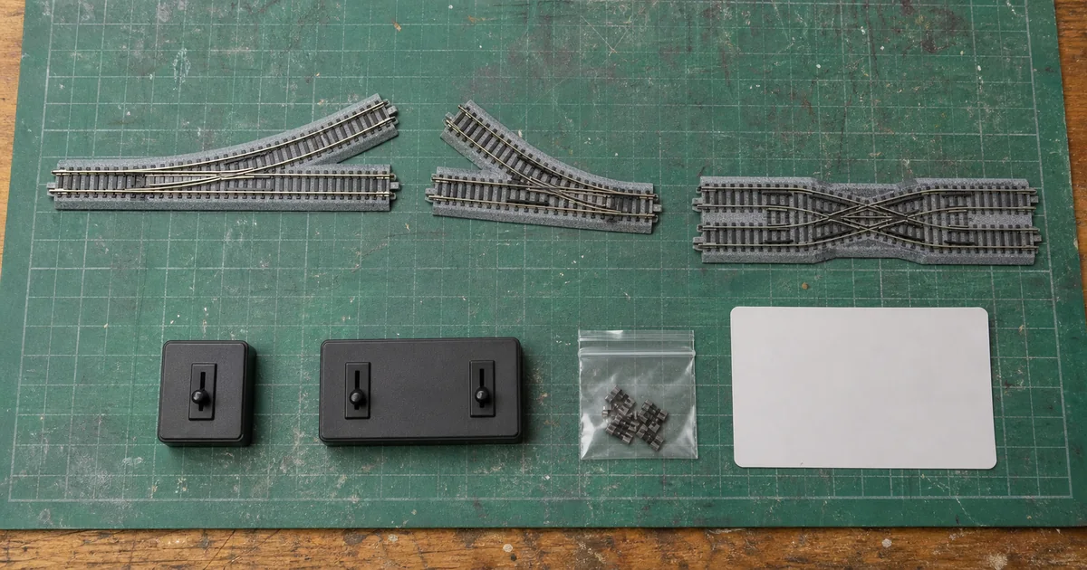
Begin with the brand-specific KATO #4 vs #6 guide or TOMIX point guide. Use the feeder guide for the wider power district and the fault tree when symptoms are not isolated to one turnout.
Four electrical questions, not one label
| Question | What to determine | Failure if assumed |
|---|---|---|
| Is the frog live? | Continuity from frog to each rail in both positions. | Unexpected dead zone or opposite-polarity short. |
| Is polarity switched? | Which device changes frog phase and whether it follows point position. | Booster trip when a wheel bridges the boundary. |
| Is power routed? | Whether the unselected exit remains energized. | Dead siding, back-feed or an invalid feeder assumption. |
| Are frog rails isolated? | Required gaps or insulated joiners in the exact maker plan. | Two supplies or phases meet through the turnout. |
What official and first-party sources establish
| Source | Verified point | Boundary |
|---|---|---|
| NCE | Separates DCC short prevention from loss-of-pickup stalling and describes insulated, dead-metal and powered-frog cases. | Not a wiring map for every turnout. |
| Digitrax KB611 | For the named KATO N #4, reports non-power-routing and insulated-frog settings for best DCC performance; advises ohmmeter verification. | Does not define KATO #6 or another production design. |
| Digitrax Norcross | Documents all-live and power-routing turnout behavior and treats point, closure and frog rails as separately understood paths. | Its demonstration layout is not your installation. |
| PECO | Currently lists the SL-U395F as an N Code 55 medium-radius right-hand Unifrog turnout. | The product name alone is not its complete wiring plan. |
| NMRA guidance | Frames powered versus dead frog as an engineering choice and emphasizes wiring to avoid shorts. | Does not override current maker instructions. |
The four-gate frog decision
1. Identity gate
GO when exact product, production variant, rail code and official instructions are recorded.
2. Continuity gate
GO when every stock, point, closure, frog and exit rail is mapped in both positions.
3. Protection gate
GO when gaps, feeders, frog switching, current protection and detection boundaries are explicit.
4. Fleet gate
GO when the least-forgiving locomotive passes every route slowly in both directions without stall or trip.
Exclusive tool 1: pickup bridge-margin calculator
Measure the longest electrically dead path along the actual wheel route and the effective span between the locomotive's live pickup points. The arithmetic margin helps screen stall risk; wheel cleanliness, suspension, turnout geometry and contact timing still govern.
Symptom-to-evidence matrix
| Symptom | First distinction | Evidence to collect |
|---|---|---|
| Locomotive stops, system stays on | Pickup interruption or unpowered route. | Dead-path length, live pickup wheels, route continuity and point contact. |
| Booster/power pack trips | Opposite polarity or back-feed. | Frog phase, gaps, feeders and point position at the instant of trip. |
| Only one route is dead | Power routing versus missing feeder. | Exit-rail continuity in both positions and downstream feed plan. |
| Only one direction fails | Pickup sequencing or mechanical lift. | Facing/trailing slow-motion video, wheel contact and frog approach. |
| Failure began after ballast | Contamination or movement. | Point clearance, flangeway, contact faces, rail height and mechanism freedom. |
Exclusive tool 2: turnout electrical release record
| Record | Minimum evidence | Reopen trigger |
|---|---|---|
| Identity passport | Brand, SKU, version, rail code, top/underside photos and maker plan. | Replacement turnout or changed setting. |
| Continuity map | Every rail and frog state in both point positions with power off. | Soldering, jumper, contact or mechanism work. |
| Isolation/feed map | Gaps, insulated joiners, feeders, frog switch and protection district. | New feeder, crossing, return loop or detection block. |
| Fleet proof | Governing locomotive and train over every route, direction and test speed. | New wheels, decoder, consist or operating move. |
| Scenery hold point | Points, flangeways, contacts and drive remain clean and serviceable. | Paint, ballast, weathering or access change. |
Six steps from identification to release
1. Record the exact turnout
Photograph the top and underside, record brand, product number, rail code, frog type, routing settings, control method and manufacturer instructions.
2. Map continuity with power disconnected
Use a meter to record which stock, point, closure, frog and exit rails connect in both turnout positions; do not infer the map from appearance or a different product.
3. Separate stall and short risks
Measure the electrically dead path against the locomotive's effective pickup span, then identify every metal frog or route whose polarity can oppose an approaching wheel.
4. Apply the exact isolation and feeder plan
Follow the named manufacturer's diagram for gaps, insulated joiners, frog switching and downstream feeders; never copy a generic diagram onto an unverified turnout.
5. Bench-test every route
With current protection active, check frog polarity and route power in both positions, then hand-roll and power the governing locomotive through every facing and trailing movement.
6. Issue a turnout release record
Record continuity, isolation, feeder, polarity, locomotive and speed results; reopen the release after any wiring, wheel, point, ballast or control change.
Railway-culture answer: a turnout is an inspection zone
FRA's automated track inspection research explicitly targets switches and frogs as assets of interest, while its compliance material treats switch points, frogs, guardrails and related components as distinct inspection items. The modeling analogy is limited but strong: release the whole turnout as a mapped system, not just the visible frog.
Official and first-party sources
Checked 2026-08-25. Product behavior is limited to the named source and model. Prices and forum anecdotes are excluded from factual claims.
- NCE — DCC-friendly turnout, stall and short distinction
- Digitrax — KATO N #4 settings and ohmmeter verification
- Digitrax — turnout rail paths and power-routing concepts
- PECO — SL-U395F N Code 55 Unifrog product identity
- NMRA Australia — powered and dead frog guidance
- FRA — inspection imagery for switches and frogs
FAQ
What is a turnout frog in N scale?
The frog is the crossing area where wheel flanges pass through the intersecting rails of a turnout. It may be insulated, electrically dead, powered, power-routed or configurable depending on the exact product. Identify it from the maker's documentation and a continuity map.
Is an insulated frog always DCC friendly?
An insulated frog avoids one common polarity-short path, but 'DCC friendly' does not guarantee uninterrupted pickup. NCE explicitly separates short-circuit prevention from locomotives stalling through loss of power. Test the shortest effective pickup span.
Does a powered frog work with DCC?
Yes, when its polarity, isolation and switching match the exact turnout and route. A powered metal frog can improve electrical continuity but can also create a short if polarity is wrong. Follow the manufacturer's diagram and test both positions.
Do all N scale turnouts need frog wiring?
No. Some have a plastic insulated frog, some provide a frog feed, and some include internal or configurable routing. The wiring requirement belongs to the exact product and layout topology, not N scale as a whole.
What does power routing mean on a turnout?
Power routing means turnout position changes which route or rail sections receive track power. It is separate from the mechanical route and from the question of whether the frog itself is powered. Map both positions before adding feeders.
How can I tell whether a turnout frog is dead?
Disconnect track power and use a continuity meter to map the frog and adjacent rails in both point positions. Compare the result with the exact maker instructions. A metal-looking frog is not proof that it is energized.
Why does a short N scale locomotive stall on a turnout?
Its effective live pickup may not bridge the electrically dead section, or dirty wheels, lifted wheels, poor point contact or an unpowered route may interrupt current. Measure the dead path, inspect pickup wheels and test slowly in both directions.
Why does a DCC booster trip at a turnout frog?
A metal wheel may bridge rails of opposite phase, the powered frog may have the wrong polarity, or isolation may not match the route. Stop, disconnect power and verify the exact continuity and feeder map before retrying.
How should a KATO #4 turnout be set for DCC?
Digitrax reports that KATO and Digitrax recommend non-power-routing with the frog screw insulated for best DCC performance on the named N scale #4 product. It also warns that some labeling may be reversed, so verify with an ohmmeter.
What is a PECO Unifrog turnout?
Unifrog is PECO's configurable frog design used on named product families, including the current N Code 55 SL-U395F listing. Do not transfer a wiring assumption from Electrofrog, Insulfrog or another scale; use the exact plan sheet.
Can a frog juicer replace turnout testing?
No. An automatic polarity device may correct a DCC frog phase, but it does not prove gauge, wheel pickup, route feeding, detection compatibility or mechanical alignment. Test the full installed turnout and protection response.
When should a turnout electrical release be reopened?
Reopen it after changing turnout, routing setting, feeder, gap, insulated joiner, frog switch, decoder, wheelset, ballast, point alignment or operating move. A previous PASS belongs only to the documented state.

