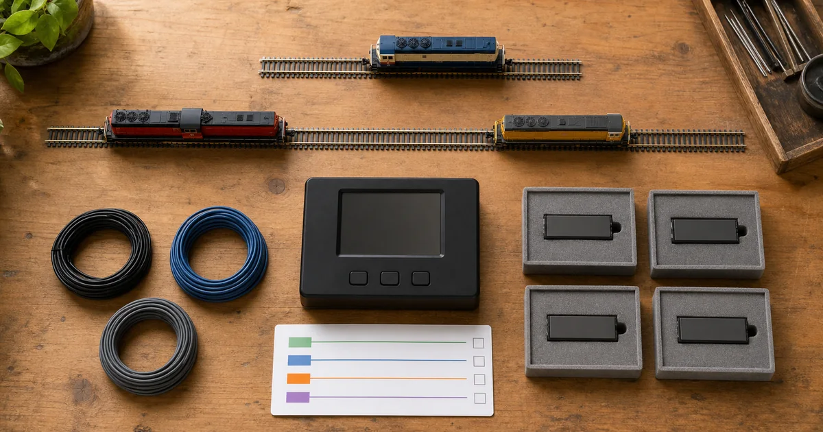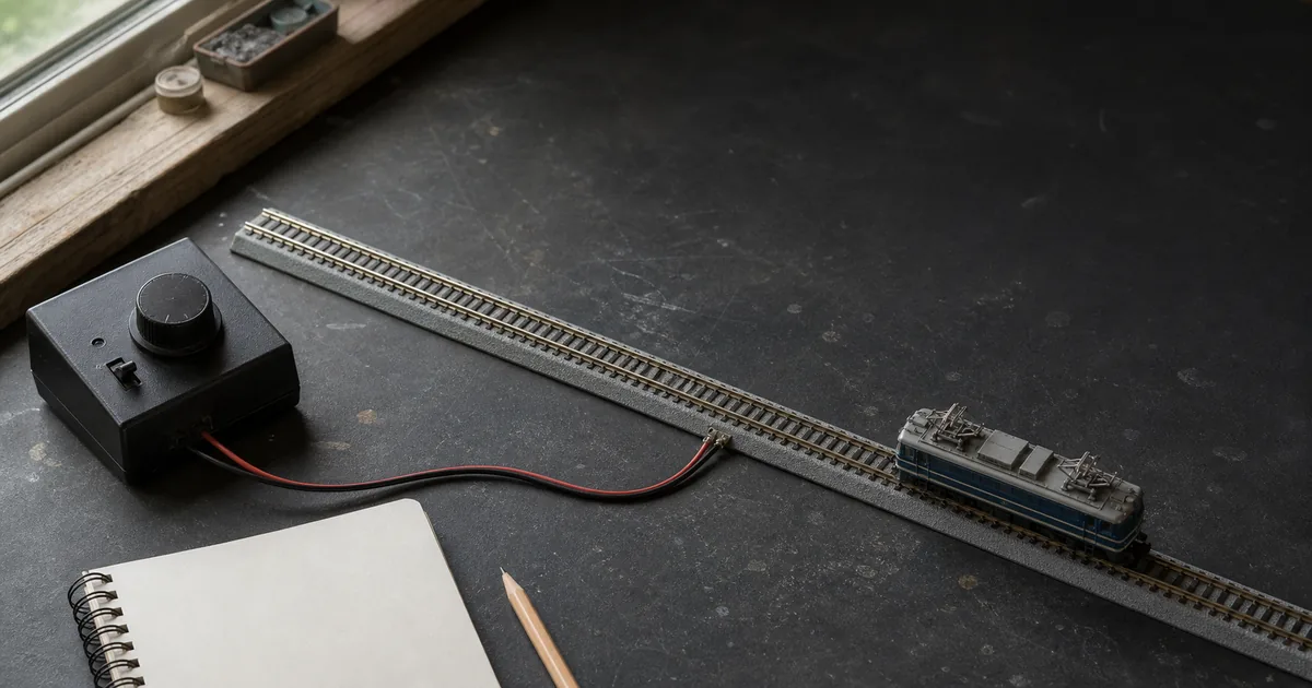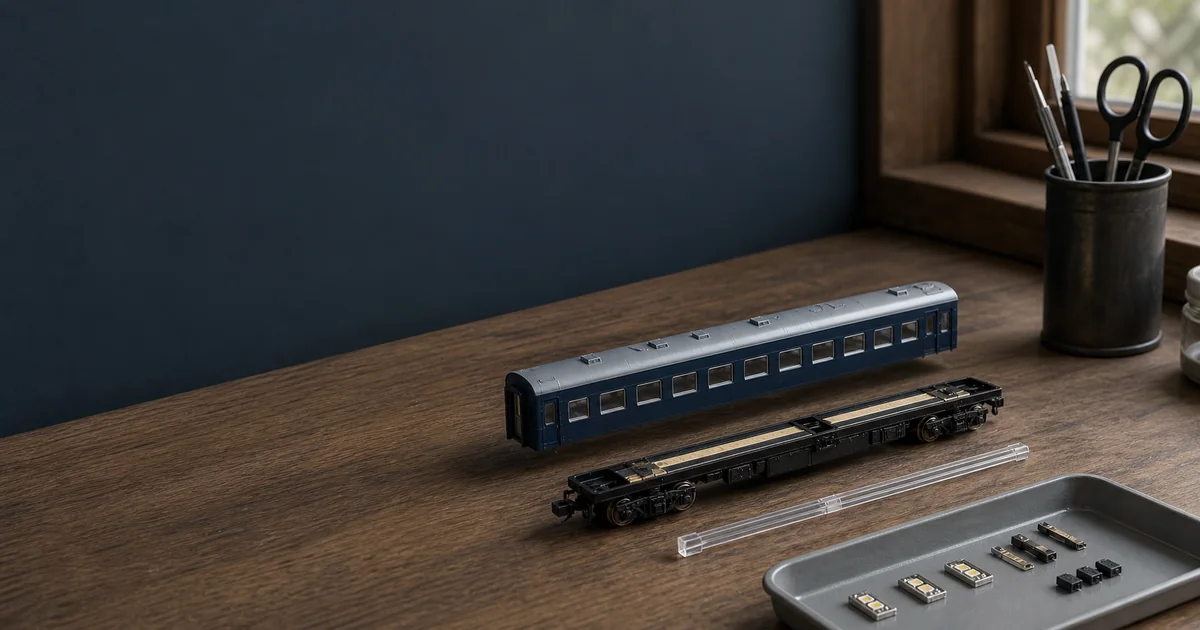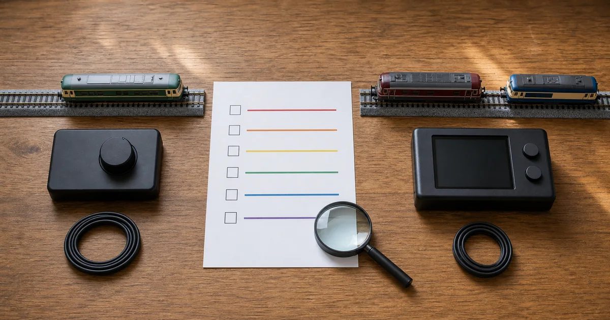
The useful difference: control boundary
Analogue DC varies track voltage and polarity, so the electrical section controls the locomotives standing in it. Two independent trains need separate circuits or electrically isolated blocks assigned to controllers. DCC places a digital command signal on the rails; a mobile decoder interprets packets addressed to its locomotive and drives that motor and its documented functions. This is why several decoder-equipped locomotives can share a powered route while obeying different commands.
That distinction is real, but the slogan “DC controls the track; DCC controls the train” hides the work around it. The NMRA's TN-9 says a DC supply usually drives one or a few locomotives in one train, while DCC can drive many vehicles from a power station. The same note also warns that a layout which worked on DC may need wiring updates for DCC because current, voltage loss and protection still matter. DCC reduces block switching used only for train selection; it does not eliminate feeders, reliable joints, short-circuit protection or diagnosis.
| Question | Analogue DC | DCC | Evidence to record |
|---|---|---|---|
| What selects a locomotive? | The powered block or circuit it occupies | An address interpreted by its decoder | Track diagram, block switches or decoder roster |
| Multiple trains on one route | Needs blocks, separate circuits or operational separation | Possible when every locomotive is decoder-equipped and system capacity is adequate | Train count, shared-route conflicts, command-station manual |
| Vehicle preparation | Exact vehicle must suit the documented DC controller and voltage | Every controlled vehicle needs a supported decoder installation | Vehicle number, interface, motor isolation, decoder rating |
| Functions | Depend on vehicle, lighting unit and controller | Depend on decoder outputs, installation and programming | Exact light/sound board and function map |
| Infrastructure | Controller, feeders and any block controls | Command station/power station, feeders, protection, programming and decoders | Complete system list, not one headline component |
Operating-goal matrix: what are you buying control for?
Start with the timetable, not the electronics shelf. The matrix below does not score one system as “advanced.” It exposes whether a simpler DC solution already meets the job or whether DCC removes a real operating constraint.
| Operating goal | DC path | DCC path | Decision gate |
|---|---|---|---|
| One train on one loop | One appropriate controller and feeder can be a complete solution | Works, but independent addressing provides little benefit by itself | Do not convert merely to replace a working knob |
| Two independent loops | One documented controller output per isolated circuit | One suitably rated system may control both decoder-equipped trains | Compare the complete equipment already owned |
| Several locomotives sharing a yard or route | Block design and cab assignment manage conflicts | Addresses reduce selection by block, while turnouts and collision avoidance still need operators | DCC has a direct operational benefit only if the fleet passes conversion |
| Independent sound or locomotive functions | Limited to what the exact DC-compatible product provides | Possible only with matching decoder outputs, installation and system controls | Require the function map, not the word “DCC” |
| Stationary or interior lighting | May be supported by an exact vehicle/light/controller combination | May be addressable with the correct function decoder and wiring | Lighting alone does not make DCC necessary |
| Large legacy fleet | Existing locomotives may remain usable without opening them | Each powered vehicle becomes a separate evidence and installation project | Audit the whole fleet before buying the command station |
ROKHELM decision rule: first find the least complex path that passes the operating goal. Then compare the work, reversibility and support of the complete alternatives. Avoid fixed price claims: controllers, decoders, installation services, availability and import costs change by market and date.
DCC Ready, Equipped and KATO DCC Friendly are different claims
DCC Ready is not the same as DCC Equipped. The NMRA beginner material describes a DCC-ready locomotive as prepared to accept components; it is not evidence that a decoder has already been installed. The exact socket, blanking plug, space, approved decoder and any analogue-mode behavior remain product questions. “Factory DCC” or “DCC Equipped” indicates an installed decoder, but the protocol, function map and whether it can run on DC still come from that decoder's instructions.
KATO's official boundary is narrower and clearer. A vehicle explicitly marked DCC Friendly accepts the designated KATO Friendly decoder without soldering or modification. KATO separates motor, cab-light and interior-light decoder roles and says Friendly decoders cannot be used in non-KATO vehicles. For a KATO vehicle not marked Friendly, KATO says wiring and soldering are required and the decoder must be chosen by scale and purpose; even then, a decoder may not support another maker's vehicle.
TOMIX's current FAQ states that TOMIX products do not support DCC. Treat that as an official support boundary. A third-party hard-wire project may exist, but it is not thereby TOMIX-approved, reversible or suitable for this general guide. If the exact vehicle and decoder maker do not document motor isolation, space, current and lighting connections, the status is HOLD.
Fleet conversion audit: four gates before one purchase
1. Documentation gate
PASS only when a current maker page, vehicle instruction or decoder instruction identifies the exact vehicle and installation path. A train name, brand or shop description is HOLD.
2. Electrical and mechanical gate
Record interface, motor isolation, decoder space, motor-current rating, lighting-board connections and any cutting or soldering. An unresolved isolation or rating question is STOP.
3. System and function gate
Confirm decoder protocol, command station, programming method, intended functions and power/protection plan. Standards improve interoperability; they do not make every handset, bus or connector universal.
4. Reversibility and proof gate
Keep original parts, use one healthy locomotive and a separate test track, and verify low-speed running, direction, current functions and heat before repeating the work across a fleet.
Address 00 is system-specific, not a migration plan
Some DCC systems implement “zero stretching” so a conventional non-decoder locomotive can move as Address 00. That optional feature is not a property of every DCC system and is not a safe reason to avoid the fleet audit.
Digitrax documents one conventional locomotive at Address 00 on applicable systems, but warns that DCC signals make heat build in a motor and that long-term use can eventually damage it. NCE explicitly says it does not support zero stretching and warns that a motor without a decoder may overheat, with coreless or low-inductance motors particularly vulnerable. The safe conclusion is not “Address 00 works carefully.” It is: check the exact command station and locomotive documentation, and do not put a non-decoder vehicle on DCC track unless both explicitly authorize the use.
Keep DC and DCC outputs apart
Never connect a DC controller and a DCC output to the same rails at the same time. A layout that changes modes needs a documented break-before-make isolation arrangement designed for its exact equipment. For a first conversion, ROKHELM's conservative method is simpler: use a physically separate test track, disconnect the DC supply, connect only the DCC system under test and follow its manual. This prevents a selector error from joining two power sources.
Do not assume old DC wiring is automatically ready for DCC. NMRA TN-9 explains that DCC may increase power requirements and that voltage loss can prevent protection from tripping properly during a short. Treat bus size, feeder attachment, current capacity and protection as design inputs. The feeder and voltage-drop guide covers those checks; the troubleshooting matrix helps isolate a fault before any decoder work.
Six-step DC-to-DCC decision workflow
1. Define the operating job
Write the exact problem you want the control system to solve: train count, shared routes, independent functions, shunting, lighting or sound. Do not buy DCC merely because it is the newer category.
2. Inventory every powered vehicle
Record maker, exact product number, present DC or decoder state, motor type if documented, lighting board, available interface and current running condition. Unknown fields remain HOLD.
3. Pass the decoder-support gate
For each vehicle, require an exact manufacturer or decoder-maker installation path covering interface, motor isolation, space, current and functions. A DCC Ready or DCC Friendly label applies only within its documented boundary.
4. Compare complete system paths
Compare the full DC block-control path with the full DCC path: controller or command station, feeders, protection, decoders, programming method, lighting and any installation work. Do not substitute a headline price for a complete bill of requirements.
5. Plan an isolated first conversion
Choose one healthy, documented locomotive and a separate test track. Keep the DC supply disconnected while DCC is connected, follow the exact system manual and preserve every original part.
6. Prove one locomotive before scaling
Verify address selection, direction, low-speed control, current functions, heat, sound and reliable running on the real route. Convert the rest only after the first boundary passes and the operating benefit is still worth the fleet work.
Railway modelling culture: how DCC became a shared language
The NMRA says it began the effort to establish a uniform command-control standard in 1994. That standardization enabled command stations and decoders from multiple manufacturers to communicate through a shared track-signal language. The modelling lesson is precise: a standard can support interoperability at the interfaces it defines, but it does not make every handset, command bus, connector, installation method or manufacturer support policy interchangeable.
Official and first-party sources
Checked 2026-08-12. Standards, firmware, product support and decoder instructions can change. Each source controls only the system or product it names; the operating-goal matrix, four-gate audit and isolated-first-conversion rule are ROKHELM editorial tools.
- NMRA Beginner's Guide to Command Control and DCC — addressed train control, decoders and standardization history
- NMRA Standards and Recommended Practices index — current DCC electrical and interface document register
- NMRA TN-9 Wiring for DC and DCC — electrical properties, wiring, voltage loss and protection
- NMRA Motive Power and Rolling Stock guide — DCC Ready and factory-equipped terminology
- KATO DCC Friendly FAQ — marked-vehicle and designated-decoder boundary
- KATO non-DCC-Friendly conversion FAQ — wiring, soldering and decoder-selection limits
- TOMIX official FAQ — DCC support, DC voltage and conditional constant lighting
- Digitrax Address 00 technical note — optional analogue operation and motor-heating warning
- NCE zero-stretching support note — unsupported feature and motor-risk boundary
- Digitrax locomotive-conversion guidance — start with a healthy motor and pickup system
Plan the control job before the conversion
Frequently asked questions
What is the core difference between DC and DCC?
With analogue DC, the controller changes the voltage and polarity of a track section, so locomotives in that section respond to the same electrical condition. With DCC, a command station sends digital packets through the rails and a decoder in each addressed locomotive controls its motor and documented functions. DCC changes the control unit from track section to vehicle; it does not remove the need for sound wiring, feeders and protection.
Is DCC always better than DC for N scale?
No. The better system is the one that solves the operating job with supported equipment and acceptable conversion work. DC can be a complete answer for one train or separately switched sections. DCC becomes valuable when independent locomotives must share routes or when exact decoder-supported functions matter. Compare both complete paths rather than ranking the acronyms.
Can DC control two trains independently?
Yes, when the layout is divided into electrically isolated blocks or separate circuits and each is assigned to the appropriate controller. The locomotives are still controlled by the electrical condition of the block they occupy. DCC can address multiple decoder-equipped locomotives on the same powered route without using block selection solely for train control.
Does DCC Ready mean a decoder is installed?
No. DCC Ready generally means the maker has provided a documented path for installing a decoder; the exact interface, blanking plug, space and approved decoder still need checking. DCC Equipped or Factory DCC indicates a decoder is installed, but its protocol, functions and analogue-mode behavior still come from the exact product and decoder instructions.
Can a DCC-equipped locomotive run on DC?
Only when the exact decoder and vehicle documentation support analogue operation and that mode is enabled. Do not infer dual-mode behavior from the words DCC Equipped alone. Check the decoder manual, voltage limits and function behavior before placing it on a DC layout.
Is KATO DCC Friendly a universal decoder socket?
No. KATO says DCC Friendly applies to vehicles explicitly marked for its designated Friendly decoders, installed without soldering or modification. It separates motor, cab-light and interior-light decoder roles and says the Friendly decoders cannot be used in non-KATO vehicles. A non-Friendly KATO vehicle may require wiring and soldering under a separate documented conversion path.
Does TOMIX officially support DCC conversion?
TOMIX's current official FAQ says TOMIX products do not support DCC. That is the manufacturer's support boundary. It does not prove that every third-party modification is physically impossible, but an unofficial hard-wire project must not be represented as TOMIX-approved or warranty-safe.
Is Address 00 a universal way to run a DC locomotive on DCC?
No. Address 00, also called zero stretching, is an optional system feature rather than a universal DCC capability. Digitrax documents it on specified systems but warns against long-term use because heat can build in the motor. NCE explicitly does not support zero stretching and warns that non-decoder motors, especially coreless or low-inductance types, may heat rapidly.
What is the practical difference between Digitrax and NCE on Address 00?
Digitrax documents control of one conventional locomotive as Address 00 on applicable systems, while warning that prolonged use can overheat and eventually damage the motor. NCE states that it does not support zero stretching at all. Follow the exact command-station and locomotive manuals; never generalize one maker's feature to another system.
Can DC and DCC power the same track?
Do not connect a DC controller and a DCC output to the same rails at the same time. If one layout must switch between them, use a documented, break-before-make isolation arrangement designed for the exact equipment, verify the dead state and follow both manufacturers' wiring instructions. ROKHELM's conservative first-conversion method uses a separate test track so the two supplies cannot meet.
Do I need DCC for interior lights?
No. Interior lighting can work on analogue DC when the exact vehicle, light unit and controller support it; TOMIX, for example, documents stationary constant lighting only with a compatible vehicle and CL-function Power Unit. DCC is relevant when a supported decoder and wiring path provide independent functions. The track-control acronym alone does not establish lighting compatibility.
When should I stop a DIY DCC conversion?
Stop when the exact installation path is missing, the motor-isolation test is unknown, the decoder current or function rating is unresolved, the shell or board requires undocumented cutting, or the locomotive already runs poorly on DC. Smoke, odor, abnormal heat, repeated short protection or damaged wiring means disconnect power and seek manufacturer or qualified service support rather than retrying.