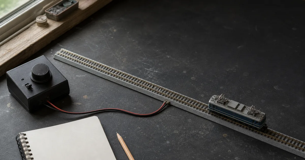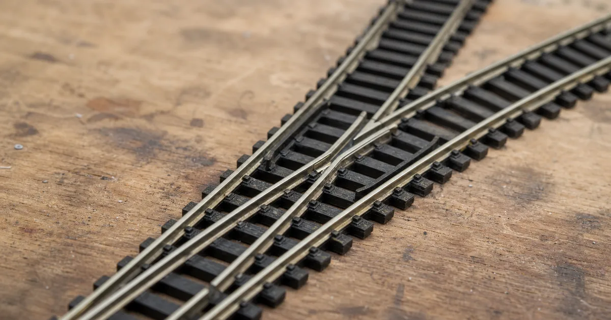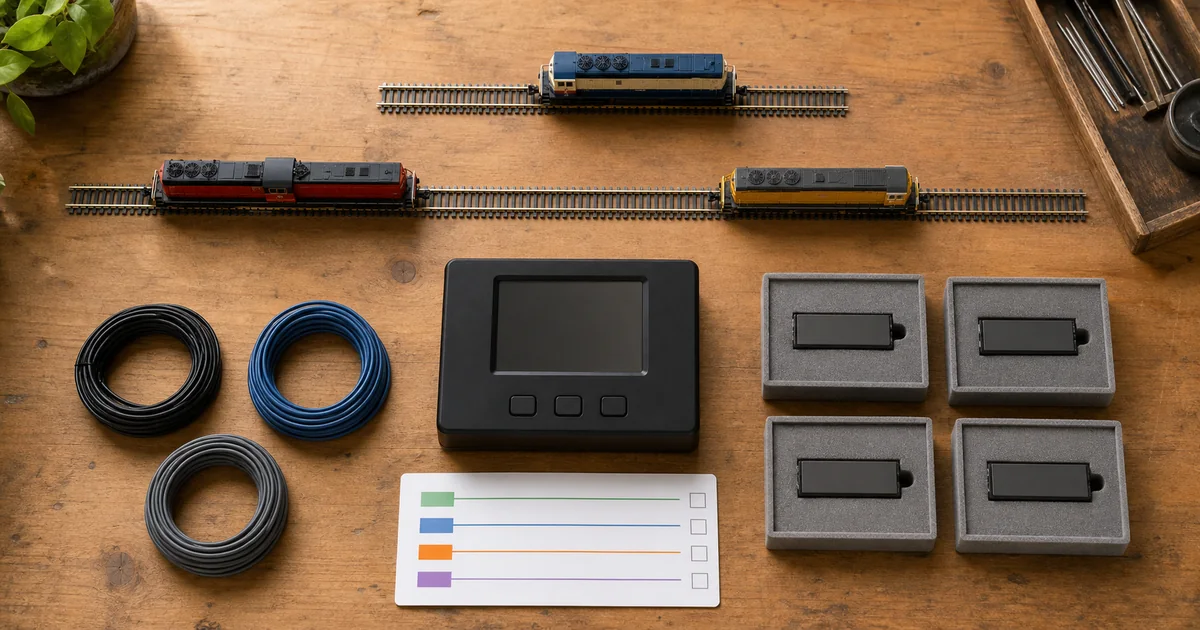
Confirm rail and frog behavior with the turnout-frog guide, compare KATO geometry with the #4 vs #6 guide, and keep automation inputs distinct with the block-detection guide.
Actuator-to-output matrix
| Actuator family | Decoder output must establish | Common mismatch |
|---|---|---|
| Bipolar two-wire solenoid | Reversing polarity and a supported pulse/current for the exact turnout. KATO USA identifies this drive for Unitrack turnouts. | A decoder intended for a three-wire twin-coil or continuous load. |
| Twin-coil snap motor | Correct common/coil wiring, pulse duration, surge capability and any capacitive-discharge mode specified by the decoder. | Holding a coil continuously or exceeding simultaneous-output limits. |
| Slow-motion stall motor | Continuous reversing output within the motor and decoder ratings, with supported end-of-travel behavior. | Using a momentary-only pulse output or treating stall current as irrelevant. |
| Servo | A real servo interface, suitable supply, travel endpoints and motion settings documented by that controller. | Connecting a servo to a motor/coil output because both have three wires. |
| Lights or relays | Correct DC/AC behavior, continuous duty, polarity, current limiting and isolation for the exact load. | Assuming a turnout output is a universal accessory supply. |
What official and first-party sources establish
| Source | Verified point | Boundary |
|---|---|---|
| NMRA S-9.2.1 | Defines Basic and Extended Accessory Decoder packet formats for simple functions such as switch machines and lights. | Packet interoperability does not guarantee that an output electrically matches every actuator. |
| KATO USA | States that Unitrack turnouts use bipolar solenoid drive and require a decoder supporting that drive. | It does not make every KATO turnout/decoder combination identical. |
| Digitrax | DS74 supports solenoid or slow-motion modes; DS51K1 lists exact KATO compatibility and a 0.5 A rating. | One model's features and limits do not transfer to another stationary decoder. |
| NCE | Separates decoder families for slow motion, twin-coil snap motors and KATO-style turnouts; Switch-Kat permits supported local momentary controls. | A remembered command state is not universal physical-position feedback. |
| Network Rail | Explains that prototype points are interlocked with signals so a failed point prevents a proceed indication. | Prototype interlocking is operating culture, not a hobby decoder safety certification. |
Four Go/No-Go gates
1. Identity gate
GO when turnout SKU, actuator wires, voltage, current and pulse/continuous duty are documented.
2. Output gate
GO when the decoder explicitly supports the actuator, load, duty, simultaneous count and intended supply.
3. Control gate
GO when accessory address, command-station notation, local inputs and route commands are uniquely mapped.
4. Position gate
GO when both physical point positions, obstruction behavior, power cycle and train-through route are observed.
Exclusive tool 1: simultaneous-load checker
Enter values from the exact actuator, decoder and supply documentation. This arithmetic screens one operating scenario; it does not certify pulse shape, voltage, duty cycle or connector temperature.
Fault matrix
| Symptom | Do not assume | Next evidence |
|---|---|---|
| Clicks but does not throw | That pulse duration is the only issue. | Actuator type, obstruction, voltage at load, wiring polarity and current limit. |
| Buzzes or heats | That another command will free it. | Remove power; inspect continuous/pulse mode, end stop, obstruction and output compatibility. |
| Works alone, fails in route | That addresses are wrong. | Simultaneous demand, supply sag, route timing and decoder route/output limits. |
| Throttle state is wrong | That the points physically failed. | Distinguish commanded state, remembered state, local control and real position feedback. |
| Wrong turnout responds | That track power is noisy. | One-output address test, board/subaddress translation and duplicate-address ledger. |
Exclusive tool 2: turnout-control passport
| Record row | Minimum evidence | Release condition |
|---|---|---|
| Actuator | Turnout SKU, actuator family, wires, voltage, current, duty and mechanical throw. | No inferred values from scale or plug appearance. |
| Decoder/output | Model, firmware, channel, mode, per-output and simultaneous limits, supply and DCC input. | Exact first-party compatibility chain recorded. |
| Address map | Throttle number, decoder/board notation, output, route membership and label at the turnout. | One command moves only the intended turnout. |
| Feedback map | Commanded state, local input, physical contact/sensor and consuming panel or logic. | No displayed command is represented as physical proof without feedback. |
| Reopen list | Actuator, decoder, supply, address, route, firmware, local control or feedback change. | Any trigger returns the turnout to bench and route release. |
Six steps from actuator identity to route release
1. Identify the exact turnout actuator
Record the turnout SKU, actuator wiring, required drive polarity, pulse or continuous duty, rated voltage and measured or documented operating current before choosing a decoder.
2. Match the decoder output
Select a decoder whose manufacturer explicitly supports that actuator type, duty, current and number of simultaneous outputs; confirm separate supply, DCC input and local-control requirements.
3. Bench-test one channel
With track power isolated while wiring, connect one turnout exactly as documented, then prove both directions, end-of-travel behavior and repeated operation before installing multiple channels.
4. Assign and record one address
Follow the decoder and command-station instructions to program one accessory address, record any board/subaddress translation, and verify that only the intended output responds.
5. Add local control and feedback separately
Install only supported momentary buttons, inputs or feedback contacts, then verify that a command indication is not being mistaken for the turnout's measured physical position.
6. Release every route event
Test normal and reverse commands, power cycling, simultaneous route commands, stall or obstruction response, manual/local control and the train route over the points; retain reopen triggers.
Railway-culture answer: command is not proof of position
Network Rail explains that points are interlocked with signals: if a point fails, the protecting signal cannot authorize the train to proceed. The modeling analogy is useful but limited—a DCC accessory command is an instruction, not automatically a verified physical route. Observe the points or use supported feedback before route-dependent automation.
Official and first-party sources
Checked 2026-08-27. Recheck the exact current product manual before wiring or programming.
- NMRA — S-9.2.1 DCC Extended Packet Formats
- NMRA — documents under revision
- KATO USA — Unitrack and DCC FAQ
- Digitrax — DS74 stationary decoder
- Digitrax — DS51K1 KATO turnout decoder
- NCE — switch/accessory decoder categories
- NCE — Switch-Kat documentation
- Network Rail — signals and points explained
FAQ
What is a DCC accessory decoder?
It receives DCC accessory packets and drives stationary functions such as turnout motors or lights. It is distinct from a mobile locomotive decoder and must match the connected load.
Does N scale require a special turnout decoder?
Scale alone is not the deciding factor. Match the exact turnout actuator, wiring, voltage, current, duty cycle, address method and control system; some products list explicit N scale compatibility.
Can any accessory decoder operate a KATO Unitrack turnout?
No. KATO USA says Unitrack turnouts use a bipolar solenoid drive and advises choosing a decoder that supports bipolar drive. Verify the exact turnout and decoder combination.
What is the difference between pulse and continuous output?
A pulse output energizes an actuator briefly, while a continuous output remains energized for loads designed for that duty. Applying the wrong duty can cause failure or overheating; follow both manuals.
Can one decoder output throw a crossover?
Only when the exact decoder manufacturer permits the actuator count and combined load. NCE says one Switch-Kat can drive two KATO solenoids, but that fact must not be generalized to other products.
Is a turnout address the same as a locomotive address?
It uses an accessory packet and address scheme, not a mobile-locomotive command. The throttle may display a simple number, while the decoder manual may describe board and output addressing differently.
Should turnout decoders use track power or a separate supply?
Follow the exact product. Some stationary decoders offer or require a separate supply, while others connect to DCC track power. Record both command and load power paths in the passport.
Does the throttle display prove the turnout moved?
Not by itself. A command or remembered state is not physical position feedback. Route release should include direct observation or a supported feedback contact and a train-through test.
Can I keep fascia pushbuttons with DCC control?
Only with supported inputs and switch types. NCE's Switch-Kat documentation permits optional momentary pushbuttons and warns that continuous-contact toggles prevent DCC control.
Why does a turnout buzz or overheat?
Remove power and check actuator type, pulse versus continuous mode, end-of-travel behavior, obstruction, wiring and voltage/current limits. Do not solve it by repeatedly commanding the output.
Can a turnout decoder also provide route feedback?
Some products have inputs or integrate with a layout bus, but capability varies. Separate commanded state, local input, physical-position feedback and route logic in the design record.
When should a turnout-decoder release be reopened?
Reopen it after changing turnout, actuator, decoder, supply, firmware, address, output mode, route, local controls, feedback wiring or simultaneous-command behavior, or after new stalls, heat or incomplete motion.