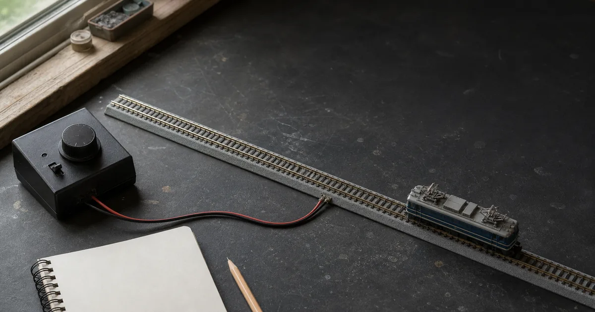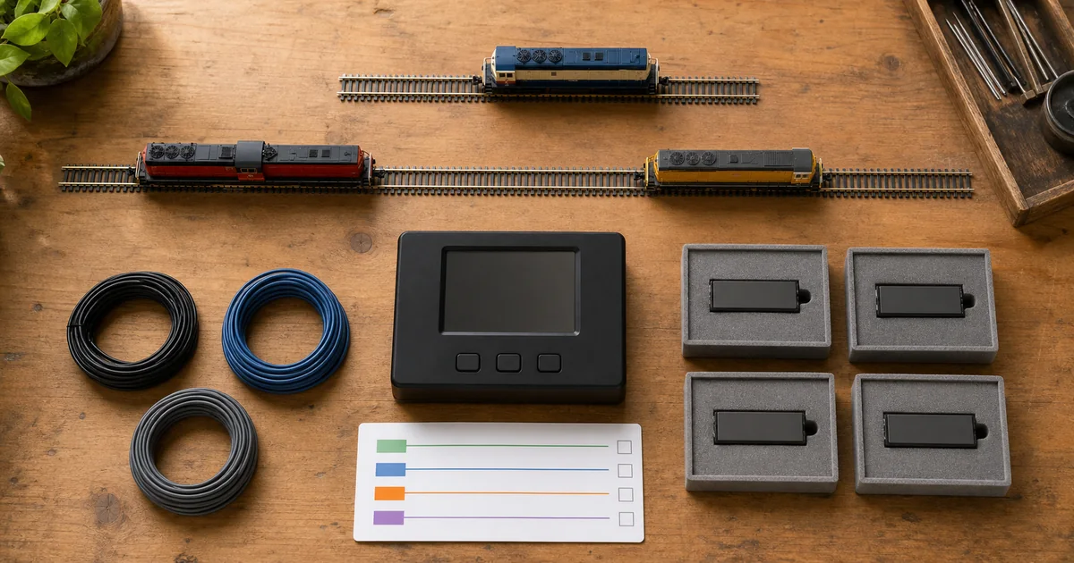
Map fault protection first with the power-district guide, preserve reverse-section boundaries with the reverse-loop guide, and confirm feeder integrity with the feeder-wiring guide.
Four layers that solve different problems
| Layer | Question answered | Typical failure |
|---|---|---|
| Detection section | Which physical rails should share one occupied/clear answer? | A gap, turnout route or hidden siding is placed outside the intended answer. |
| Detector | Is sufficient current or another target signal present in that section? | A feeder bypasses the sensor, or an accessory creates permanent current draw. |
| Reporting path | Which address carries the detector state to a panel, bus or computer? | Duplicate, swapped or stale addresses make the right detector appear in the wrong place. |
| Logic/output | What should occupancy do—light an LED, reserve a route, animate or influence signals? | Software logic is blamed for an unstable local detector, or occupancy alone is mistaken for movement authority. |
What first-party documentation establishes
| Source | Verified point | Design boundary |
|---|---|---|
| NCE BD20 | Current draw triggers occupancy; all feeders for its section must pass through the detector, and unpowered cars need a detectable load. | Its wiring and sensitivity details do not automatically transfer to another detector topology. |
| Digitrax BDL716 | The current product provides 16 DCC detection sections and can be arranged for two booster areas. | Channel count does not decide where your operational boundaries belong. |
| Digitrax BXP88 | Occupancy, transponding and power management are distinct functions, even when one product combines them. | Basic occupancy does not identify a specific locomotive. |
| JMRI | A software Sensor represents an input state; a Block uses an occupancy Sensor and mainly supports signaling or layout logic. | Software cannot repair an electrically unstable section. |
| Network Rail | Prototype track circuits feed a wider signaling system and are designed to fail toward an occupied indication; current projects may layer track circuits with axle counters. | Prototype safety architecture is context, not a model-railroad wiring recipe. |
Four gates before buying channels
1. Question gate
GO when each section answers one named operating need: hidden-track indication, route protection, automation or signaling input.
2. Boundary gate
GO when gaps, turnouts, boosters, breakers, auto-reversers and all feeders are drawn together.
3. Hardware gate
GO when detector topology, current capacity, reporting bus and lowest detectable load are documented from first-party instructions.
4. Evidence gate
GO when clear, occupied, low-current, power-off and boundary-crossing states can be tested locally and end to end.
Exclusive tool 1: detection-section capacity planner
Count operating answers, not track pieces. This tool adds a documented reserve for future boundaries; it does not select a detector or claim that every route needs its own channel.
Detection fault matrix
| Observed state | Do not assume | Next controlled evidence |
|---|---|---|
| Always occupied | That software mapping is wrong. | Disconnect reporting, inspect bypass feeds and detected accessories, then test local clear with the exact sensitivity setup. |
| Locomotive seen, tail lost | That the whole train is protected. | Test the last intended detectable vehicle; document resistor-wheel or lighting loads where required. |
| Flicker at one joint | That debounce is the first remedy. | Inspect rail, wheels, pickup, gaps, feeder continuity and the detector’s local state before software timing. |
| Wrong panel section | That track wiring is defective. | Activate one detector at a time and trace detector channel, hardware address and software Sensor name. |
| Clear when power is off | That clear means safe. | Define power-loss behavior, local power indication and logic handling; release only the documented fail state. |
Exclusive tool 2: section-release record
| Record row | Minimum evidence | Release condition |
|---|---|---|
| Section passport | Name, drawing limits, gap rail(s), turnouts, power district, breaker/reverser and every feeder. | One physical answer matches one documented name. |
| Detector passport | Model, channel, topology, capacity, sensitivity setting, supply and current firmware/manual. | No substituted hardware or undocumented adjustment. |
| Reporting map | Local indicator, bus address, software system/user names, Block and consuming logic. | One induced occupancy changes only the intended state. |
| Rolling-stock grid | Locomotive, lit coach, lowest-current equipped car, longest train and both directions. | Required vehicles remain detected across every boundary. |
| Reopen list | Gap, feeder, detector, sensitivity, power, address, logic or rolling-stock-load changes. | Any trigger returns the section to local and end-to-end tests. |
Six steps from operating question to release
1. Define the operating question
Decide whether each indication will protect a route, show hidden staging, drive a panel, feed JMRI or support signaling; mark where one answer must change to another.
2. Draw power and detection boundaries
Map boosters, breakers, auto-reversers, gaps, common returns and every feeder before selecting detector channels; keep power districts and detection sections as separate concepts.
3. Assign one complete current path
Follow the exact detector manual so every feeder for the monitored section passes through its sensing path and no bypass feed or accessory creates a permanent occupied state.
4. Commission locally
With downstream reporting disconnected, prove clear, locomotive occupied, low-current vehicle occupied and power-off behavior at the detector or its local indicator.
5. Commission the reporting chain
Map each hardware input to one unique system address and software sensor, then verify that the intended panel or block changes without swapping adjacent sections.
6. Release every boundary event
Run the longest and lowest-current intended train across each entry, exit, turnout and reversing boundary in both directions; record latency, flicker, false occupancy and reopen triggers.
Railway-culture answer: train detection is evidence, not authority
Network Rail explains that a prototype track circuit supplies train-presence evidence to a broader signaling system and normally fails toward an occupied state. Its 2026 Thameslink work adds axle counters alongside track circuits for resilience. The modeling lesson is architectural: name the sensor, its failure state and the logic that consumes it. Prototype equipment and safety rules do not define hobby wiring.
Official and first-party sources
Checked 2026-08-27. Product capacity and wiring must be rechecked against the exact current manual before purchase or installation.
- NCE — BD20 Block Detector
- Digitrax — BDL716 product page
- Digitrax — BDL716 instructions
- Digitrax — BXP88 occupancy, transponding and power management
- JMRI — Sensors documentation
- JMRI — Blocks documentation
- Network Rail — track circuits explained
- Network Rail — Thameslink Core dual detection
FAQ
What is DCC block detection?
It is sensing whether a defined track section is occupied, commonly by detecting current drawn through one rail feed, then reporting that state to an indicator, layout bus or software.
Is a detection section the same as a power district?
No. A power district manages capacity or faults; a detection section answers an occupancy question. One power district can contain many detection sections, subject to the selected hardware instructions.
Does block detection control signals directly?
Not necessarily. NCE states that its BD20 detects current and needs an input or logic path for broader reporting; detection, reporting, logic and signal driving are distinct layers.
Will an unpowered N scale freight car be detected?
Not by current sensing unless it draws enough current. NCE identifies lights or resistor wheel sets as ways unpowered rolling stock can create a detectable load; verify the exact detector and vehicle.
Must every feeder pass through the detector?
For the NCE BD20 example, yes: NCE says all feeders for that section must pass through the BD20. Treat the exact product manual as authoritative because detector topologies vary.
Why does a block always show occupied?
Common causes include a bypass feeder, accessory or indicator drawing from the detected rail, leakage, long cable capacitance, contamination, incorrect common wiring or an address mapping error. Isolate one layer at a time.
Why does occupancy flicker as a train moves?
Check wheel and rail pickup, detector sensitivity, vehicle load, gaps, feeder continuity, connector security and debounce settings. Do not hide an electrical dropout with software until the local detector state is stable.
Can JMRI detect a train without detector hardware?
JMRI represents the state reported by an input sensor; it does not make ordinary track occupancy electrically observable by itself. Hardware and an interface are still required for real detection.
Do I need resistor wheel sets on every car?
No universal rule applies. Define what must remain detectable after the locomotive leaves a section, then equip and test enough vehicles to satisfy that operating requirement with the chosen hardware.
Should turnouts be their own detection sections?
Only when the operating or signaling question requires an independent answer. A turnout throat may need separate detection for route protection, but unnecessary boundaries add wiring and reporting complexity.
Can occupancy detection identify which locomotive is present?
Basic occupancy answers occupied or clear. Identification needs an additional technology such as transponding and compatible reporting; Digitrax distinguishes those functions in its product documentation.
When should a detection-section release be reopened?
Reopen it after changing gaps, feeders, detector type, sensitivity, booster or breaker topology, auto-reverser, reporting address, software mapping, rolling-stock detection load or the route question itself.