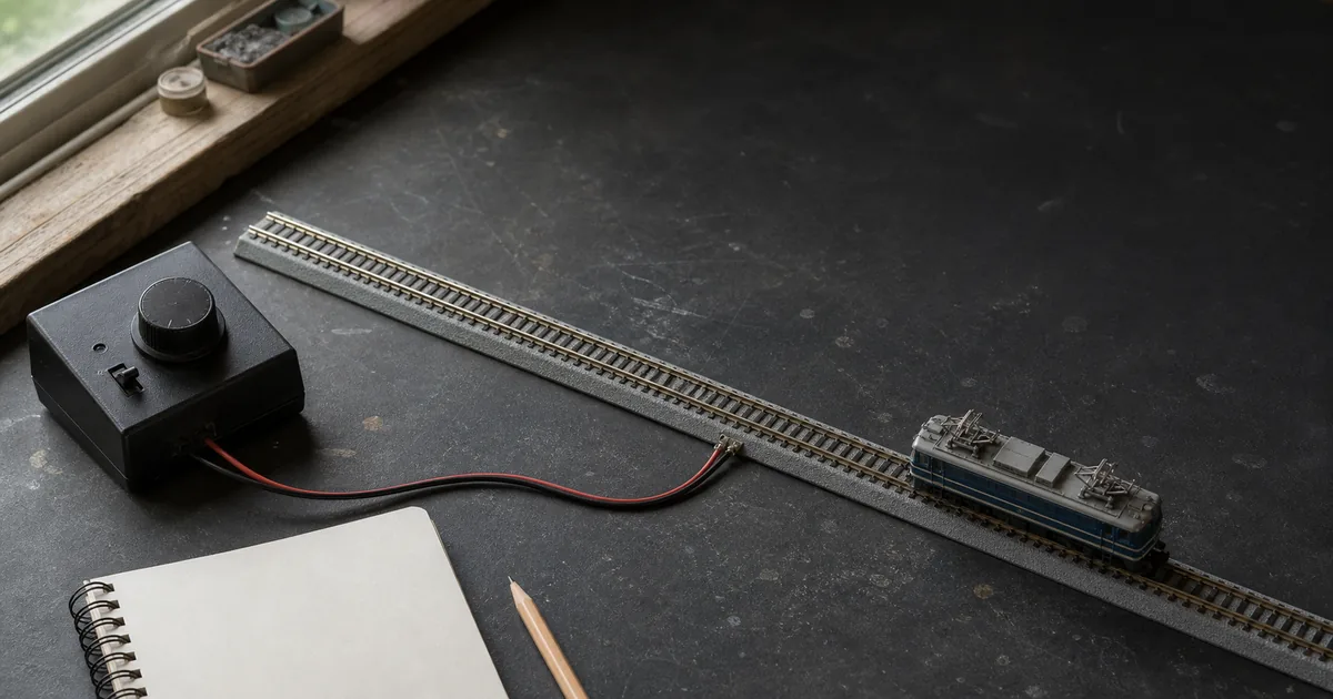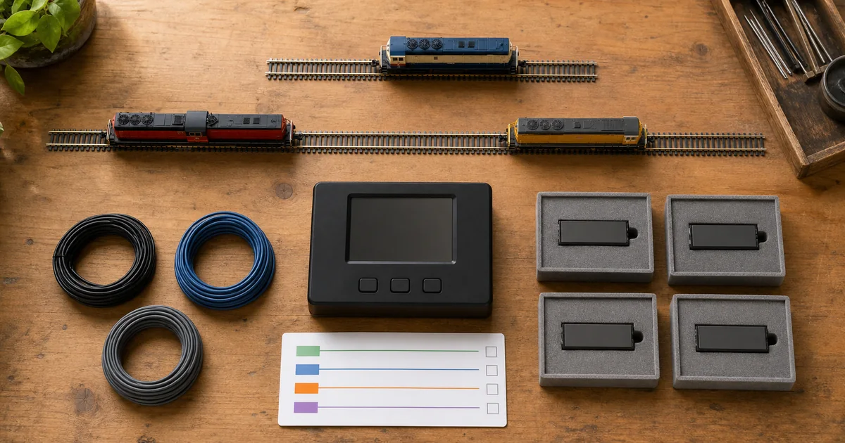
Commission the command chain with the DCC setup guide, prove delivery with the feeder guide, and treat a phase-changing route separately with the reverse-loop guide.
Four jobs that search results often blur
| Element | What it does | What it does not prove |
|---|---|---|
| Booster | Raises the command-station signal to a documented power level for its district. | That a distant short will be detected through every installed wire path. |
| Protected subdistrict | A downstream breaker isolates a local fault while the shared booster may continue elsewhere. | Any increase in the booster’s total available current. |
| Reversing district | An approved auto-reverser changes phase when a train bridges unlike rail phases. | General overload capacity or turnout alignment. |
| Operational isolation | A documented switch or boundary removes power for storage, work or diagnosis. | Automatic short-circuit protection unless rated and designed for it. |
What first-party sources establish
| Source | Verified point | Design limit |
|---|---|---|
| NCE | Separates the need for a booster from circuit-breaker protection and discusses booster-fed power districts. | Use the exact NCE system and device instructions. |
| Digitrax PM74 | Four detection sections can provide short management; recommended wiring feeds and monitors both rails between double-gap pairs. | Its manual says downstream and booster fault logic can interact, so installation testing is mandatory. |
| Digitrax support | A protected turnout-control segment can remain powered while a train-caused short is isolated elsewhere. | A product example, not permission to improvise ratings. |
| Atlas | DCC blocks can isolate shorts; some breakers are not compatible with common-rail wiring. | Confirm topology before reusing legacy DC common rail. |
| DCC-EX | Bus and feeder resistance affect power delivery and short detection; districts are not a substitute for adequate wiring. | Choose wire and protection from the complete installed path. |
Four gates before buying hardware
1. Purpose gate
GO when each boundary has one stated job: capacity, containment, reversing or service isolation.
2. Load gate
GO when measured normal load plus documented additions stay inside the exact continuous limits.
3. Coordination gate
GO when the downstream device clears a local fault before the upstream booster shuts down.
4. Reach gate
GO when the approved fault test passes at both the nearest and electrically farthest rails.
Exclusive tool 1: operating-load headroom screen
Enter the continuous limit published for the exact district path—not a forum estimate. Measure a representative normal operating case, then add the documented or measured load you plan to introduce.
Boundary-event fault matrix
| Observed event | Likely distinction | Evidence to collect |
|---|---|---|
| Only one district trips | Containment may be working as intended. | Fault location, downstream indication and unaffected-district status. |
| Booster and all districts shut down | Upstream device won the timing race or the fault bypasses the breaker. | One-line diagram, device settings and every cross-boundary feeder. |
| Near test passes; far test fails | Loop resistance may keep fault current below reliable detection. | Bus/feeder route, joints, voltage under load and manufacturer wire guidance. |
| Trips only with normal trains | Operating load, inrush or an intermittent vehicle fault may be the cause. | Measured current, vehicle-by-vehicle substitution and event timing. |
| Chatter at a reverse boundary | Reversing and overcurrent devices may be competing. | Exact topology, response settings and boundary bridge event. |
Exclusive tool 2: district release record
| Record | Minimum evidence | Reopen trigger |
|---|---|---|
| Purpose passport | District name, owner device and reason for every two-rail boundary. | Operating plan or topology change. |
| One-line power map | Supply, command station, boosters, breakers, buses, feeders and gaps. | Any wiring or device substitution. |
| Load ledger | Exact limits, measured normal load, planned addition and date. | Fleet, lighting, sound or accessory change. |
| Coordination record | Manufacturer-approved settings and which device clears first. | Firmware, trip or booster change. |
| Fault proof | Near/far result for every district and unaffected-section observation. | Unexpected shutdown or failed isolation. |
Six steps from boundary to release
1. Define the reason for every boundary
Mark each proposed district as a capacity boundary, a protected subdistrict, a reversing section or an operational isolation; do not treat those purposes as interchangeable.
2. Draw both rails and every feeder
Map the booster output, protection device, both bus wires, every feeder and every two-rail gap so no feeder bypasses the intended boundary.
3. Measure normal and planned load
Measure representative operating current and add documented planned loads, then compare the sum with the exact continuous limit published for the chosen equipment.
4. Coordinate protection settings
Follow the manufacturer instructions so the downstream circuit breaker clears its subdistrict before the upstream booster shuts down, without exceeding any wire or device rating.
5. Test faults at the farthest rails
With rolling stock removed and manufacturer-approved protection active, perform the specified short-response test at the nearest and farthest point of every protected district.
6. Issue and maintain a district release
Record boundaries, feeds, measured loads, device settings and fault results; reopen the release after any wiring, booster, protection, detection or load change.
Railway-culture answer: sectionalization limits impact
Network Rail says its third rail is divided into electrical sections with circuit breakers at each end so each section can be switched as required, and normally fed from both ends for efficiency and resilience. The model-railway lesson is only the architecture: named boundaries, known switching and recorded isolation make faults manageable. Prototype traction voltages, protection rules and work procedures must never be copied to a model layout.
Official and first-party sources
Checked 2026-08-25. Product claims apply only to the named source and model; no universal trip current, locomotive count or wire size is asserted.
- NCE — boosters and power districts
- NCE — DCC circuit-breaker myth versus fact
- NCE — when a booster is needed
- Digitrax — PM74 power-manager instructions
- Digitrax — circuit breakers for districts and subdistricts
- Atlas — DCC layout wiring and common-rail caution
- DCC-EX — track bus, feeder and power-district wiring
- Network Rail — third-rail electrical sections and circuit breakers
FAQ
What is a DCC power district?
A power district is a separately fed electrical section of track. It may have its own booster for added capacity or be a protected subdistrict fed through a circuit breaker from a shared booster; document which meaning applies.
Does a DCC circuit breaker add more power?
No. A circuit breaker limits the effect of a short and can isolate a protected subdistrict, but it does not increase the booster’s available current. Add capacity only through equipment approved for that purpose.
When does an N scale layout need another booster?
Consider another booster when measured and planned simultaneous load cannot remain within the exact system’s documented capacity, or when the manufacturer’s architecture requires one. Layout size alone is not a sufficient test.
How many trains can one DCC district run?
There is no universal train count. Decoder, motor, sound, lighting, accessory and idle loads vary, so measure the intended operating case and compare it with the exact equipment documentation.
Do power districts need gaps in both rails?
Use the exact manufacturer diagram. Modern protected subdistrict examples commonly isolate both rails, and Digitrax’s PM74 instructions specify double-gap pairs for the recommended two-rail protection arrangement.
Can adjacent districts share a common rail?
Do not assume they can. Atlas notes that some circuit breakers are not compatible with common-rail wiring. Confirm the exact booster and protection-device instructions before retaining any shared return.
Is a reversing district the same as a protected district?
No. A reversing controller resolves a phase mismatch at a reversing boundary; a circuit-breaker mode contains a fault. Some power managers can be configured for either role, but the wiring and purpose must be documented separately.
Why does the whole layout shut down during one short?
The fault may be outside a protected boundary, a feeder may bypass it, or the upstream booster may trip before the downstream device. Test coordination at both near and far rails using the exact manufacturer procedure.
Should I raise the trip current when a breaker keeps tripping?
Not as a first response. Remove power, find the load or fault and verify wiring, device limits and coordination. Digitrax explicitly advises using the lowest setting consistent with reliable operation for its PM42.
Can turnout motors and track share a DCC district?
They can in some designs, but a track short may then remove the power needed to correct a mis-set turnout. Separate accessory power or a deliberately protected control section can preserve recovery, subject to the device instructions.
Where should I test a DCC circuit breaker?
Test the specified response at the nearest and electrically farthest rails in every subdistrict. A passing test beside the breaker does not prove that feeder and bus resistance will allow detection at the far end.
When should a district release be reopened?
Reopen it after changing boundaries, gaps, feeders, wire size, booster, breaker, settings, detection, accessories or the simultaneous operating load, and after any unexplained shutdown or failure to isolate.