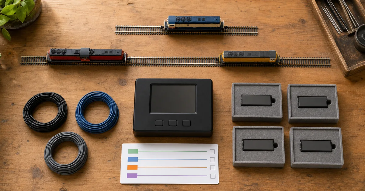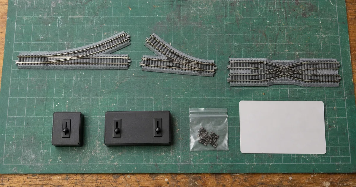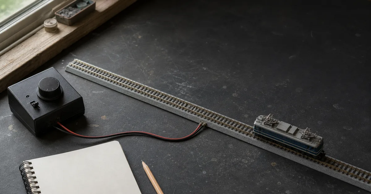
Use the DCC guide to commission the control system, the feeder guide to prove voltage delivery and the frog guide when a turnout adds a separate polarity or pickup fault.
First identify the topology
| Track form | Trace test | Typical controlled section |
|---|---|---|
| Balloon/reverse loop | One rail returns to meet the opposite rail at the same throat. | The loop between two double-gapped boundaries. |
| Wye | Following either fork can turn the train and exchange rail sides. | A documented leg or district that can contain the whole train. |
| Turntable | A rotating bridge can present its left rail to the opposite approach rail. | The bridge, subject to the exact product's internal contacts. |
| Crossover route | Track geometry alone is not proof; trace each rail through the complete route. | Only the section that actually returns rail A to rail B. |
What official and first-party sources establish
| Source | Verified point | Boundary |
|---|---|---|
| NMRA | Reverse loops and wyes need both rails gapped; a DPDT or suitable auto-reversing circuit can control the isolated section. | Beginner guidance, not a device-specific terminal map. |
| Digitrax AR1 | The reversing section is fed from the controller output and its length is determined by the maximum train using it. | Exact AR1 instructions only; other devices differ. |
| Digitrax KB7/KB596 | DCC phase changes need not alter locomotive speed or direction, and an AR1 does not itself throw the turnout. | Route automation remains a separate design task. |
| KATO | A current planning example marks insulated Unijoiners and a reversing switch for a DC reversing route. | A representative named plan, not universal wiring. |
| Atlas | DCC layout diagrams may use auto-reversers and require isolation from simultaneous DC power or a programming track. | Use the exact layout and equipment instructions. |
The four-gate reversing decision
1. Topology gate
GO when a color trace proves exactly where one rail meets the opposite rail.
2. Containment gate
GO when the full conductive train fits between the two boundary pairs with margin.
3. Control gate
GO when phase control, turnout control, booster protection and detection each have one documented owner.
4. Event gate
GO when every entry and exit produces one clean event without shutdown, chatter or a second bridged boundary.
Exclusive tool 1: reversing-section containment calculator
Measure between the innermost points of the two double-gap boundary pairs. Measure the full conductive span of the governing train—not just locomotive length—because metal wheels, common pickup buses and lighted cars can carry current across a boundary.
Boundary-event fault matrix
| Observed event | Likely distinction | Evidence to collect |
|---|---|---|
| Booster shuts down at one gap | Reverser did not win the protection race or a feed bypasses isolation. | Device settings, booster timing, boundary continuity and every feeder. |
| Repeated clicking/chatter | Both boundaries bridged, competing devices or unsuitable threshold. | Conductive train span, wheel positions and controller event log. |
| Turnout is misaligned | Route control is separate from section phase. | Turnout command, detection trigger and clearance timing. |
| Only lighted train fails | Coach pickups extend the conductive span. | Each car's wheel pickups and electrical interconnections. |
| Works one way only | Asymmetric gap, feeder, turnout or approach route. | Four boundary-direction tests and rail-by-rail continuity. |
Exclusive tool 2: reversing-section release record
| Record | Minimum evidence | Reopen trigger |
|---|---|---|
| Topology passport | Rail-color trace, route list, exact gap locations and photographs. | Track, turnout or turntable change. |
| Containment ledger | Usable section length, governing train and conductive span. | Longer consist, metal wheels or lighting pickup. |
| Power map | Input, output, feeders, protection district, detection and programming-track separation. | Any feeder, booster or detector change. |
| Control map | Phase owner, turnout owner, trigger, threshold and fail-safe route. | Firmware, decoder or automation change. |
| Event proof | Every boundary in both directions with the governing train and one clean response. | Shutdown, chatter, derailment or intermittent pickup. |
Six steps from rail trace to release
1. Trace the two rails
Mark one rail from the main line through the loop, wye or turntable; if it returns against the opposite rail, identify the complete reversing topology before wiring.
2. Define and size one isolated section
Choose two boundaries, gap both rails at each boundary and make the isolated section longer than the longest train whose conductive wheels can bridge those boundaries.
3. Separate track phase from turnout control
Document which device changes track phase and which device throws each turnout; an auto-reverser does not automatically align the route unless its exact instructions provide that function.
4. Wire with track power off
Follow the exact manufacturer diagram, feed the reversing section only from the approved controller output and prevent any normal-bus feeder from bypassing an isolation gap.
5. Test every boundary event
With current protection active, run the governing train across each boundary separately in both directions and record one clean phase change without booster shutdown or repeated chatter.
6. Issue a reversing-section release
Record topology, gap locations, feeders, controller settings, longest conductive train and test results; reopen the release after any related wiring, wheelset, train-length or route change.
Railway-culture answer: a loop is an operating route
Chicago's Loop 'L' opened as a downtown elevated circuit connecting lines from different sides of the city, and CTA still describes junction and signal work as central to routing several services through it. The modeling lesson is operational, not electrical: a loop is a complete route with junction ownership and clearance rules, not merely a curved piece of track.
Official and first-party sources
Checked 2026-08-25. Product behavior is limited to the named source and model. Prices, forum diagrams and unverified trip settings are excluded from factual claims.
- NMRA — reverse loops, wyes, double gaps and DPDT control
- Digitrax — AR1 installation and maximum-train section sizing
- Digitrax — automatic reversing sections under DCC
- Digitrax — phase control versus turnout control
- KATO — representative insulated-Unijoiner and reversing-switch plan
- Atlas — DCC layout wiring cautions and auto-reverser option
- CTA — official history of the Loop 'L'
FAQ
What creates a reverse loop short in N scale?
In a two-rail layout, a loop, wye or turning bridge can bring one rail back to the opposite rail. Without two-rail isolation and controlled phase or polarity, the boundary connects unlike rails and shorts the supply.
Does DCC eliminate reverse loop wiring?
No. DCC keeps the locomotive direction command independent of track phase, but the two rails still must not meet out of phase. Both ends of the reversing section need double gaps and a manual or automatic phase-changing method.
How long should a DCC reversing section be?
It must contain the longest conductive train that can bridge its two boundaries. Include locomotives, lighted cars and metal wheelsets that share current paths, then add practical clearance and prove the installed case.
Do both rails need gaps at a reverse loop?
Yes. NMRA and Digitrax guidance describe double gaps at the boundaries of a reversing loop or wye. A feeder or common return that bypasses a gap defeats the intended isolation.
Can one auto-reverser control two reverse loops?
Do not assume so. Digitrax notes that multiple reversing sections on one auto-reversing booster are acceptable only when one reversing event occurs at a time. Use the exact device instructions and operating plan.
Does an auto-reverser throw the turnout?
Not necessarily. Digitrax states that its AR1 corrects the track phase mismatch but does not throw the turnout. Route control is a separate function unless the chosen system explicitly integrates both.
Can I use a DC reversing switch on DCC?
Use only equipment explicitly approved for the control system. A manual DPDT method and a DCC auto-reverser solve related boundary problems differently; similar product names do not prove compatibility.
Why does the booster shut down before the auto-reverser acts?
The auto-reverser threshold or response may not coordinate with the booster, wiring resistance may mask the event, or the section may have an unintended feed. Stop and follow the exact device adjustment and protection instructions.
Why does an auto-reverser chatter repeatedly?
A train may bridge both boundaries, adjacent reversing devices may compete, a feeder may bypass isolation, or the trip setting may be unsuitable. Remove power and test each boundary and feed independently.
Does a wye need the same wiring as a reverse loop?
A two-rail wye creates the same rail-against-opposite-rail problem, but the isolated section and turnout sequence differ. Trace the rails, double-gap the chosen reversing leg or district and verify every possible route.
Does an N scale turntable need an auto-reverser?
It depends on the turntable's own contact design and instructions. A bridge that rotates far enough to exchange rail sides needs a controlled phase solution unless the product already provides one.
When should a reverse-loop release be reopened?
Reopen it after changing gaps, feeders, controller, booster protection, turnout logic, detection, train length, metal wheelsets, lighted cars or any route that can create a second simultaneous boundary event.