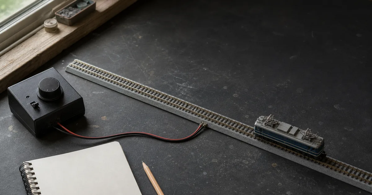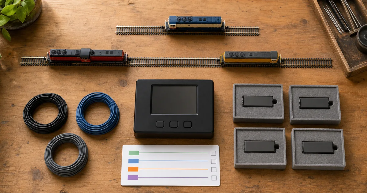
Start with the first-locomotive DCC guide, preserve power boundaries with the district guide, and diagnose delivery problems with the feeder guide.
Service Mode and POM are not substitutes
| Method | Addressing and feedback | Best controlled use |
|---|---|---|
| Service Mode | Broadcasts on the programming output or exposed track; many systems can detect decoder acknowledgements and read CVs. | Initial identity, address recovery, supported readback and wholesale configuration. |
| Programming on Main / Ops Mode | Targets a known decoder address on operational track; conventional systems may not confirm or read the value. | Supported, deliberate changes to a known locomotive without moving it to a service track. |
| Vendor software/programmer | Capabilities depend on its interface, decoder family and connection. | Only the functions and wiring explicitly documented for that combination. |
What official and first-party sources establish
| Source | Verified point | Boundary |
|---|---|---|
| NMRA S-9.2.3 | Defines Service Mode and says command stations/programmers need instructions for a low-current programming track. | The current standards index marks the document under revision; use current product manuals too. |
| NCE | Warns the Power Cab lacks a separate programming output and that a programming track may be part of a layout only when electrically isolated. | Power Cab architecture does not describe every NCE system. |
| Digitrax | Service Mode broadcasts to all connected decoders, while Ops Mode addresses a selected decoder. | Exact terminals and permitted CVs vary by product. |
| TCS CS-105 | Documents an isolated programming connection, main-output shutdown during programming and CV readback behavior. | Those actions are specific to the CS-105. |
| DCC-EX | Distinguishes Service Mode feedback/readback from POM behavior. | Use its current hardware and software instructions for implementation. |
Four gates before the first write
1. Architecture gate
GO when the exact command-station output and mode are identified from its manual.
2. Exposure gate
GO when only the intended decoder can receive Service Mode packets.
3. Baseline gate
GO when decoder identity, current address and readable starting CVs are recorded.
4. Recovery gate
GO when the old value, reset procedure and smallest functional proof are available.
Exclusive tool 1: programming-exposure checker
This screen does not inspect wiring. It forces two facts into one decision: how many decoders can receive the output, and whether the physical connection matches the exact system manual.
Programming fault matrix
| Observed result | Do not assume | Next evidence |
|---|---|---|
| No decoder acknowledgement | That the CV write failed or that a generic booster is required. | Exact mode, pickup, decoder compatibility and manufacturer diagnostics. |
| Several locomotives change address | That software selected only one decoder in Service Mode. | Every electrical path and every decoder exposed to the broadcast. |
| Readback works but locomotive will not move | That the motor path is healthy. | Address, speed step, CV29 interpretation and low-speed functional test. |
| Works in POM, not Service Mode | That the isolated track or acknowledgement path is correct. | Output selection, gaps, feeders, wheel pickup and exact service procedure. |
| Unexpected mainline movement | That the programming boundary is safe. | Remove power immediately and audit back-feed or switch-state error. |
Exclusive tool 2: CV change-and-rollback ledger
| Record | Minimum evidence | Release rule |
|---|---|---|
| Decoder passport | Vehicle, decoder maker/model, firmware if visible, system and programmer. | Exact identity confirmed before values are copied. |
| Exposure proof | Output, switch state, isolated rails and count of connected decoders. | One decoder for ordinary Service Mode work. |
| Before row | CV, readable old value, address and observed function. | Unknown values are marked unknown, never invented. |
| Change row | Requested value, method, time and reason. | One controlled change or documented group. |
| After row | Readback where supported plus functional proof and rollback result. | Release only when the intended result is reproducible. |
Six steps from isolation to release
1. Identify the exact programming architecture
Read the command-station manual and record whether Service Mode uses a dedicated output, the normal track output in another mode or an approved switching arrangement.
2. Create a one-decoder exposure boundary
Arrange the track and switching exactly as specified so only the intended decoder can receive Service Mode broadcasts and no mainline feed can back-power the section.
3. Record the baseline
Write down the locomotive, decoder, current address and every CV value that the exact system can read before making a change.
4. Change one controlled item
Use the programming method approved by the command-station and decoder instructions, change one address or CV group and record the requested value.
5. Verify readback or function
Read the value back when the system supports it; otherwise perform the smallest safe functional test that proves the intended result without assuming a write succeeded.
6. Release or roll back
Return switching to its normal state, prove the mainline cannot feed the programming output, test the locomotive at low speed and retain the before-and-after ledger for recovery.
Railway-culture answer: test away from revenue service
Network Rail describes dedicated test tracks as a safe, controlled link between innovation and operational implementation. Old Dalby opened in 1966 for Advanced Passenger Train development and today supports new and modified trains and technology without disrupting passenger or freight service. The modeling analogy is procedural: isolate the trial, record the baseline, prove the change, then release it. Prototype testing rules do not define model DCC wiring.
Official and first-party sources
Checked 2026-08-27. Product behavior is limited to the named system. Generic CV values, booster remedies and switching diagrams are excluded.
- NMRA — S-9.2.3 Service Mode standard
- NCE — Power Cab Service Mode architecture
- NCE — programming-track isolation definition
- Digitrax — Evolution Express programming instructions
- Digitrax — Service Mode versus Ops Mode
- TCS — CS-105 programming-track behavior
- DCC-EX — programming choices and feedback
- Network Rail — dedicated railway test tracks
FAQ
What is a DCC programming track?
It is an electrically controlled section used for Service Mode programming so the intended decoder can receive broadcast programming packets without exposing the rest of the fleet. The physical connection depends on the exact command station.
Is Service Mode the same as Programming on Main?
No. Service Mode broadcasts to decoders on the programming output or isolated section. Programming on Main, also called Operations Mode, addresses a selected decoder on powered layout track; available readback and commands depend on the system.
Does every DCC system have a separate programming output?
No. NCE states that the Power Cab has one pair of track wires and changes operating mode rather than providing a dedicated programming-track output. Other systems, such as the TCS CS-105, provide a dedicated connection.
Why must only one decoder be exposed in Service Mode?
Service Mode programming is generally broadcast. Digitrax and NCE warn that every decoder connected to that output can receive the command, so isolation prevents accidental fleet-wide address or CV changes.
Can the programming track be part of the layout?
It can only when the exact manufacturer-approved switching arrangement provides complete electrical isolation and prevents mainline power from back-feeding the programming output. A physically separate test track is easier to audit.
Can I drive a locomotive from the programming track onto the main line?
Only if the exact system provides an approved drive-away or switching method. A Service Mode output may be limited-energy or inactive outside programming, and connecting it directly to mainline power can damage equipment.
Why will my decoder not read back?
The system may not support readback in that mode, the decoder acknowledgement may not be detected, pickup may be poor or the wiring may be wrong. Clean only after isolating the cause and follow the exact system and decoder troubleshooting procedure.
Can sound decoders need different programming support?
Some combinations have higher acknowledgement or energy requirements, but there is no universal booster or resistor remedy. Use only the exact command-station, programmer and decoder manufacturer instructions.
Should I use POM to change a locomotive address?
Use the method explicitly supported by the command station and decoder. Digitrax notes that many decoder addresses require Service Mode, while POM is useful for supported changes directed to a known address.
What should I record before changing CV29?
Record the decoder model, current address, readable CV29 value and the exact features each intended bit controls for that decoder. Do not copy a generic value without checking the decoder instructions.
Can a programming track test a newly installed decoder safely?
A manufacturer-approved limited-energy programming output is useful for initial checks, but it does not replace verifying motor isolation, wiring, component orientation and heat with track power off before energizing.
When should the programming-track release be reopened?
Reopen it after changing the command station, programmer, switching, gaps, feeders, decoder family, software, firmware or operating procedure, and after any unexpected fleet-wide change, failed readback or back-feed indication.