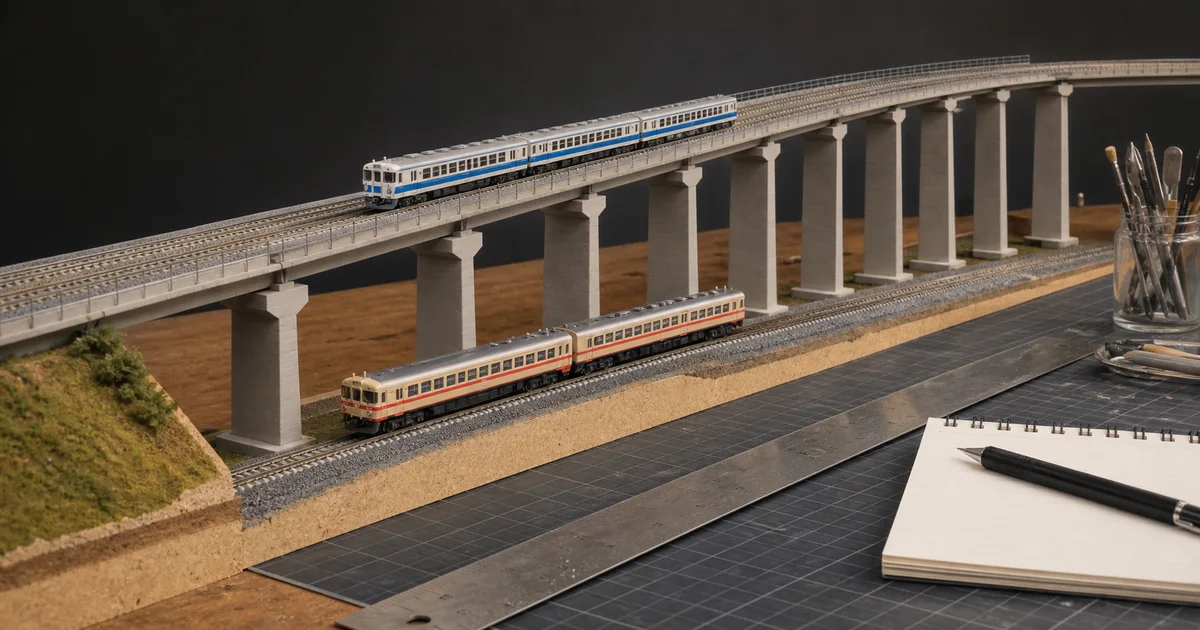
An over-under layout is not solved by choosing a pier marked 50 or 55 mm. The lower train must clear the underside of the upper structure, the upper train must climb there through a usable route, every deck and support must fit its own system, and both levels must remain recoverable after scenery. Those are four linked decisions, not one height.
Use the grade calculator for detailed rise/run work, the curve-route certificate when the ramp bends, and the track-planning release gates before locking the whole design.
The four-gate viaduct decision
1. Envelope
GO only when the tallest lower train, upper deck depth and chosen allowance are separately recorded.
2. Ramp
GO only when the constant grade plus both transitions fit and the governing train passes under load.
3. System
GO only when track, approaches, piers, joiners and accessories form a documented mechanical chain.
4. Service
GO only when both levels remain stable, cleanable and recoverable after planned scenery.
Exclusive tool 1: vertical-budget and ramp-run calculator
Enter measurements from your proposed structure and governing train. The calculator adds the three vertical layers, then estimates only the constant-grade run. It deliberately does not invent a clearance allowance or vertical-transition length.
KATO: basic, supplementary and level piers are different jobs
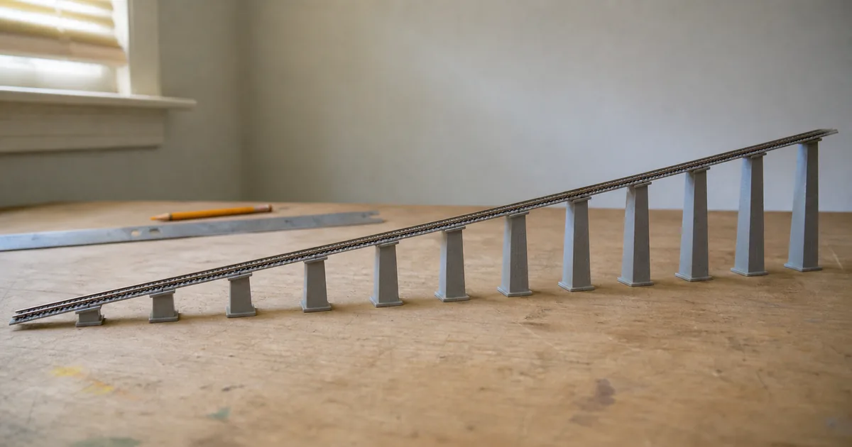
KATO's current pier page describes its family as a route system for bridges, viaducts and approaches. The 23-015-1 basic incline set contains two each of pier Nos. 1–5 plus stairs. The 23-016-1 supplementary set works with that basic set to add intermediate support, including the middle of R348-45 single-track viaduct curves. The 23-017-1 No. 5 set is the 50 mm standard-height support for level viaduct.
| KATO family | Documented role | Record before buying |
|---|---|---|
| 23-015-1 basic incline piers | Two each of Nos. 1–5, S-joiners and stairs for a single-track approach sequence. | Exact viaduct pieces, approach, intended rise and support locations. |
| 23-016-1 supplementary piers | Used with the basic set for intermediate support and more representative spacing. | Where the manufacturer diagram or chosen geometry needs the extra supports. |
| 23-017-1 No. 5 piers | Five standard 50 mm supports for a level elevated section. | Railhead height and underside clearance of the assembled structure—not 50 mm alone. |
| 23-048 / 23-049 double-track | Basic and supplementary double-track incline families; KATO documents 186 mm incline straight pieces in the double-track sequence. | Single versus double track, catenary bases, bridge pieces and the exact set instructions. |
KATO USA's current set guide also shows that a V2 viaduct package is an expansion set with specific R315 viaduct curves, straights, a truss bridge, an incline-pier set and No. 5 piers. Treat the diagram as evidence for that listed plan, not proof that the same rise, train or footprint works in a redesigned route.
TOMIX: P1–P10 defines a height sequence, not a grade percentage
TOMIX 3234 contains two sets of the ten P1–P10 pier heights for single-track inclines. TOMIX states that a ground-to-P10 approach uses the separately sold 3020 step. For level track, 3235 supplies eight P10-55 supports, while 3236 supplies eight P4-25 supports and matches one embankment layer.
| TOMIX part | Official boundary | Common planning mistake |
|---|---|---|
| 3234 PC incline piers P1–P10 | Ten heights, two sets; usable with viaduct track and bridges. | Assuming the box alone defines one grade or includes every ground transition part. |
| 3020 step | TOMIX calls for it when building from ground level to P10 with 3234. | Discovering the omitted interface only after the pier sequence is purchased. |
| 3235 P10-55 level piers | Eight constant-height P10-55 supports. | Treating 55 mm as guaranteed clearance under every deck and vehicle. |
| 3236 P4-25 level piers | Eight P4-25 supports; TOMIX says this height matches one embankment layer. | Using a level-pier set where a changing incline sequence is required. |
The TOMIX NXF layout manual places piers at track joints and distinguishes level from incline supports. That is a useful planning model: support location belongs to the exact track assembly, not to a visual spacing guess made after scenery.
Clearance is a measured envelope, not empty air
NMRA RP-7 reorganizes track-center and obstacle-clearance practice by scale, route and modeling era. It is a valuable reference, but it does not turn one number into approval for every Japanese N scale vehicle or proprietary viaduct. Check at least these layers:
| Layer | What can govern | Physical proof |
|---|---|---|
| Lower rolling stock | Roof equipment, pantograph state, sway, curve overhang and manufacturing variation. | Slowly move the tallest actual vehicle through every lower route and direction. |
| Upper structure | Deck, roadbed, rail, clips, bridge girders, wiring and any underside detail. | Measure underside to upper rail on the assembled piece, not a catalog pier alone. |
| Lateral envelope | Piers, abutments, walls, catenary masts and inside/outside body swing on curves. | Mock every obstacle at full position and hand-roll the governing vehicle. |
| Access envelope | Hands, cleaning tools, rerailing space and removable scenery. | Recover a deliberately stopped vehicle before declaring hidden track acceptable. |
Exclusive tool 2: the over-under route release certificate
A PASS belongs to one train pair and one assembled route. Record the following before glue, ballast or permanent fascia hides the evidence:
| Certificate field | Minimum record | Reopen trigger |
|---|---|---|
| Governing equipment | Exact upper and lower SKUs, consists, loads, couplers and pantograph state. | New or reconfigured train, coupler, load or operating state. |
| Vertical budget | Measured train height, allowance, deck stack, upper rail height, grade and transition lengths. | Changed deck, track, wire, height target or ramp geometry. |
| Support chain | Track, approach, bridge, pier, joiner, step and catenary-support product numbers and locations. | Moved support or substituted system component. |
| Operating proof | Hand roll, low-speed runs both directions, representative load, lower clearance and upper stability. | Strike, sway, stall, derailment or intermittent joint. |
| Service proof | Cleaning path, wiring access, rerailing/recovery test, removable scenery and inspection date. | New scenery, fascia, wiring or reduced opening. |
GO means every recorded field passes. HOLD means evidence or a complete-route test is missing. STOP means contact, instability, excessive load, an undocumented mixed-system boundary or failed recovery remains.
Six steps from train envelope to fixed viaduct
1. Define the governing trains and equipment
Record the exact upper and lower trains, their intended direction and the tallest lower-route state, including a raised pantograph or other equipment only when that state will actually be used. Measure the physical models rather than relying on scale alone.
2. Build the vertical budget
Add measured lower-train height, a user-chosen operating allowance and the actual distance from the underside of the upper structure to its railhead. The result is a planning target for upper-rail height, not a universal clearance standard.
3. Calculate the ramp run and transitions
Divide the required rise by the proposed grade as a decimal to estimate constant-grade run, then add space for both vertical transitions. Use the separate grade calculator and test the real governing train under representative load.
4. Select one documented pier and viaduct system
Choose KATO or TOMIX parts from current official pages and instructions. Record basic, supplementary, level, approach, joiner and catenary-support parts separately; do not assume a pier from one system clips securely to the other.
5. Dry-lay the entire risk area
Assemble the crossing, both transitions, adjacent curves or turnouts and supports at the positions required by the manufacturer. Mock scenery, catenary, fascia and recovery openings before gluing or fixing anything.
6. Prove operation, recovery and change control
Hand-roll and then run the complete upper and lower trains slowly in every intended direction, check body and equipment clearance, load, pier stability and recovery access, and issue a dated route certificate. Reopen it after any relevant train, geometry or structure change.
Railway-culture answer: Japanese viaducts are route infrastructure, not decoration
JRTT reports that viaducts make up 59.2 km, or 52%, of the 114.6 km Kanazawa–Tsuruga construction section it documents for the Hokuriku Shinkansen. RTRI separately places RC/PC bridges and railway viaducts inside a structure discipline concerned with design, deterioration, disaster response and maintenance. The modeling lesson is direct: an elevated line should be planned as a continuous structure with inspection and recovery access, not as isolated piers added after the track plan is finished.
Official and first-party sources
Checked 2026-08-25. Manufacturer pages establish product contents and system boundaries; NMRA provides clearance practice; JRTT and RTRI provide the prototype context. The calculator, four-gate decision and route certificate are ROKHELM editorial tools, not manufacturer or NMRA standards. Prices and availability are intentionally excluded because they change.
- KATO — UNITRACK pier families, contents, 50 mm No. 5 and supplementary-pier roles
- KATO USA — current track-set and viaduct assembly guide
- TOMIX 3234 — PC incline piers P1–P10
- TOMIX 3235 — P10-55 level piers
- TOMIX 3236 — P4-25 level piers and embankment-height boundary
- TOMIX 3020 — ground-transition step used with 3234
- TOMIX NXF2023 manual — level and incline viaduct planning
- NMRA RP-7 — track centers and obstacle-clearance framework
- JRTT — Shinkansen construction and documented viaduct route shares
- RTRI Structure Technology Division — viaduct design and maintenance context
FAQ
How much vertical clearance does an N scale viaduct need?
There is no universal number for every N scale layout. Measure the tallest lower-route vehicle in its intended operating state, choose and document an allowance, add the actual upper deck-to-rail thickness, then prove the crossing physically. NMRA clearance diagrams are useful references, but a Japanese-profile model, catenary arrangement or proprietary viaduct can create a different governing envelope.
Is a 50 mm KATO or 55 mm TOMIX pier automatically enough?
No. KATO documents 50 mm as its No. 5 standard pier height, while TOMIX P10 is a 55 mm pier, but neither label alone proves usable clearance. Railhead height, deck depth, lower-train height, pantograph state, nearby curves and your operating allowance all affect the result.
What is the difference between KATO basic and supplementary incline piers?
KATO says the 23-015-1 basic set contains two each of pier Nos. 1 through 5 plus stairs. The 23-016-1 supplementary set is used with the basic set to support intermediate positions, including the middle of R348-45 single-track viaduct curves, and to create more realistic pier spacing. It is not a substitute for the basic sequence.
What is included in TOMIX 3234 P1-P10?
TOMIX describes 3234 as two sets of ten single-track incline-pier heights, P1 through P10. Its official information says a ground-to-P10 incline also uses the separately sold 3020 step. Treat that step and every connecting structure as explicit bill-of-material items rather than assuming the pier box is a complete ramp.
What are TOMIX P4 and P10 level piers for?
TOMIX 3236 contains eight P4-25 level piers for a 25 mm level matching one embankment layer, while 3235 contains eight P10-55 level piers. They support constant-height sections; they do not replace the changing pier sequence needed for an incline.
Can KATO track use TOMIX piers, or vice versa?
Do not assume a secure mechanical fit. The manufacturers document their own piers, joiners, steps, beams and viaduct track as systems. A custom interface may be possible, but it becomes your engineered boundary and needs restraint, alignment, electrical continuity where relevant, and full route testing.
How long must the incline be?
For the constant-grade portion, run equals rise divided by grade expressed as a decimal. For example, the calculator can show the arithmetic for your chosen inputs, but you must add both vertical transitions and prove the actual train. A pier sequence does not create one fixed grade percentage unless its track spacing is also fixed.
Can an N scale curve be placed on the incline?
Only after the exact system and train pass a complete-route test. Curvature, grade, coupler angle and body swing act together, and manufacturers may specify support positions or special approach pieces. Test the real curve, transitions, viaduct sidewalls and governing train rather than approving the curve and grade separately.
Should a turnout be placed on a grade or viaduct transition?
Avoid treating that as a default arrangement. A turnout adds point, frog and branching geometry, while a vertical transition changes wheel and coupler loading. If the design requires one, use documented components, keep the critical mechanism accessible and test every route with representative trains before release.
How should pantographs and catenary affect clearance?
Decide the actual operating state first. If pantographs will run raised under wire or a height limiter, mock that exact system and test it. If they will always be lowered, record that restriction. Never use the fully raised display height as an unstated assumption or ignore a raised operating state that the layout is meant to support.
When should viaduct piers be glued down?
After the complete temporary route has passed geometry, clearance, load and access tests. Use the manufacturer's clips or joiners during proof where applicable, mark every support position, and delay irreversible scenery or adhesive until the governing trains repeatedly pass and a failed vehicle can still be recovered.
When must the viaduct route be retested?
Reopen the route certificate after adding a taller, longer or weaker train; changing pantograph or coupler state; moving a pier, curve, turnout, transition or deck; adding catenary, scenery or fascia; reducing access; or observing repeated stalls, strikes, sway or derailments. PASS belongs to the recorded route and trains, not to the product family forever.