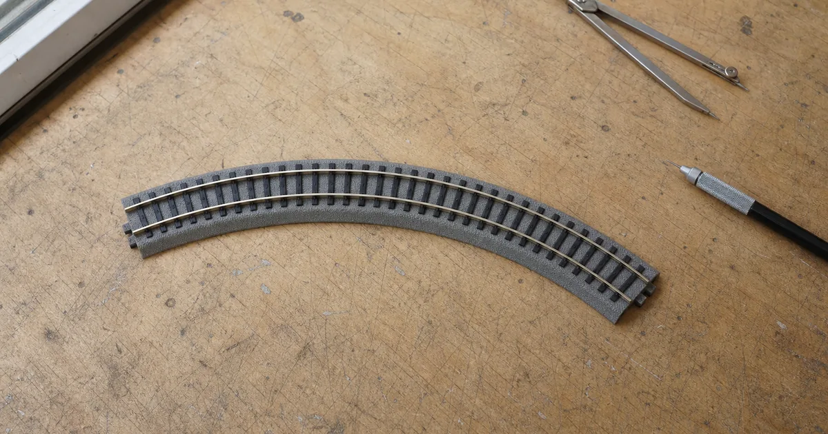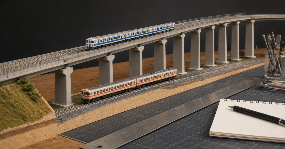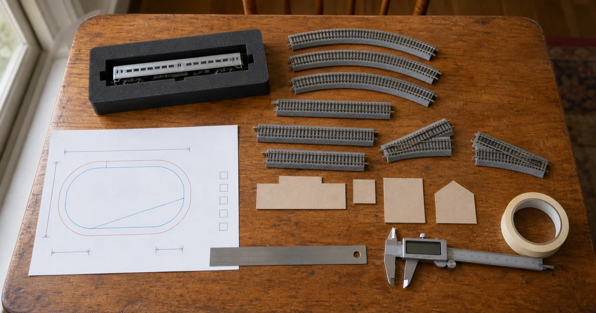
First freeze the route with the track-planning gates. If the tracks curve, pair this guide with the radius release certificate; if one passes over the other, use the vertical-clearance budget.
What 33 mm and 37 mm actually mean
| Evidence | Documented geometry | What it does not prove |
|---|---|---|
| KATO UNITRACK | KATO identifies 33 mm as its realistic standard double-track interval. Its double-track products and geometry are built around that center spacing. | Clearance for every long car, tight curve, canted section, platform or mixed-system transition. |
| TOMIX Fine Track | TOMIX defines 18.5 mm as the basic roadbed width, 37 mm as double-track spacing and 55 mm where an island platform is installed. | That any unrelated platform, structure or vehicle pair fits those dimensions. |
| NMRA RP-7.1 | Provides tangent track-center and obstacle-clearance recommendations by scale and modeling era. | Automatic approval for concentric curves; RP-7.1 explicitly sends curved cases to separate practice. |
| NMRA curved assistant | Uses tangent centers, inner radius, gauge, superelevation and governing equipment dimensions to calculate curve needs. | A substitute for measuring proprietary track, exact vehicles or structures after assembly. |
The four-gate spacing decision
1. Geometry
GO when every centerline, radius and transition is dimensioned from the exact track system.
2. Equipment
GO when the two governing trains and their operating states are recorded.
3. Sweep
GO when both toward-track envelopes are physically measured at every risk point.
4. Route
GO when both trains pass together and structures remain accessible.
Exclusive tool 1: measured swept-gap calculator
This screen uses measurements from your actual mock-up. “Toward-track reach” means the maximum lateral distance from one route's centerline toward the other route. The example inputs demonstrate the arithmetic; they are not recommended dimensions.
Why the straight answer fails on curves
NMRA RP-7.1 covers tangent track and points curved cases to RP-7.2 and RP-7.3. The reason is physical: vehicle ends move outward while the body center moves inward. With two concentric tracks, the inner train's outer sweep and the outer train's inner sweep can meet even when two stationary bodies look comfortable on straight track.
| Risk point | Governing evidence | Proof before fixing track |
|---|---|---|
| Concentric curve | Both radii, both measured vehicle sweeps, cant and direction. | Meet the two longest or widest governing vehicles at the worst angular position. |
| Reverse curve | Body swing plus coupler angle through the reversal. | Test hauled and propelled movement if both are intended. |
| Platform approach | Platform face, car ends, steps and any widening geometry. | Mock the full platform edge and stop the train at every intended position. |
| Catenary or portal | Mast, beam, pantograph state and lateral vehicle envelope. | Test the exact support location separately from train-to-train clearance. |
| Hidden route | Clearance plus hand, tool, cleaning and recovery envelope. | Recover a deliberately stopped or derailed vehicle before closing scenery. |
Exclusive tool 2: parallel-route release certificate
A PASS belongs to one documented train pair and one assembled route. Record these fields before ballast, platforms or scenery hide the evidence.
| Certificate field | Minimum record | Reopen trigger |
|---|---|---|
| Track passport | Brand, product numbers, centers, radii, turnout/crossing geometry and cant. | Any substituted track or moved centerline. |
| Governing trains | Exact SKUs, consist, direction, load, coupler and pantograph state. | New vehicle, consist or operating state. |
| Sweep ledger | Measured toward-track reach for both trains at each risk point. | New radius, speed, cant or measurement method. |
| Operating proof | Hand roll and powered meetings in every intended direction and route. | Strike, sway, derailment or intermittent joint. |
| Structure proof | Platform, catenary, tunnel, bridge, scenery and recovery access. | New structure, scenery, fascia or reduced opening. |
Six steps from centerlines to released double track
1. Record the exact system geometry
Record the track brand, product numbers, nominal center spacing, inner and outer radii, turnouts, crossings, platforms and structures. Treat KATO 33 mm and TOMIX 37 mm as system geometry, not universal clearance approvals.
2. Name the governing train pair
Choose the two exact vehicles or consists most likely to conflict and record their direction, coupler state, pantograph state and intended speed. Include the longest cars and widest equipment that will actually use the route.
3. Measure both swept half-envelopes
Dry-lay each route, mark its centerline and measure how far each governing vehicle reaches toward the adjacent track at every risk point. Measure the real models rather than estimating only from body width or scale.
4. Screen the measured gap
Subtract both measured toward-track reaches from the center-to-center spacing, then compare the remaining gap with a documented project allowance. Treat a positive screen as permission to continue testing, not final approval.
5. Run a two-train acceptance test
Mock platforms, catenary, bridge sides and scenery, then hand-roll and power both governing trains through every intended direction and meeting point at representative load and speed.
6. Issue and maintain a route certificate
Record the train pair, geometry, measured gap, allowance, test conditions and date. Reopen the certificate after any vehicle, radius, spacing, superelevation, structure or operating change.
Railway-culture answer: clearance is managed as an envelope
RTRI explains that railways set building limits around trains and developed equipment to measure the distance from trackside facilities. That prototype practice does not provide model dimensions, but it supports the planning habit: record the moving envelope and inspect the route, instead of trusting visual empty space.
Official and first-party sources
Checked 2026-08-25. Manufacturer sources establish their own geometry; NMRA provides recommended-practice structure; RTRI provides prototype clearance-inspection context. Prices and availability are excluded because they change.
- KATO — UNITRACK system and 33 mm double-track standard
- KATO — double-track products and 33-to-66 mm station widening
- TOMIX — Fine Track 18.5, 37 and 55 mm geometry
- TOMIX — Wide PC Track 37 mm double-track documentation
- NMRA RP-7.1 — tangent centers and clearance diagrams
- NMRA RP-7.6 — using the curved-track clearance assistant
- NMRA — current curved-track center and obstacle-clearance assistant
- RTRI — facility-gauge measurement for trackside clearance
FAQ
What is the standard N scale track spacing?
There is no single universal number. KATO documents 33 mm for its standard UNITRACK double-track geometry, while TOMIX documents 37 mm for Fine Track and 55 mm where an island platform is intended. NMRA recommendations vary by era and require extra analysis on curves. Use the exact system plus a physical two-train test.
Is KATO N scale double-track spacing 33 mm?
Yes, KATO's official UNITRACK material identifies 33 mm as its standard double-track center spacing. That describes compatible system geometry; it does not guarantee every vehicle pair, curve, cant, platform or mixed-brand boundary will clear.
Is TOMIX Fine Track spacing 37 mm?
Yes. TOMIX states that 18.5 mm is its basic roadbed width, 37 mm is the Fine Track double-track interval and 55 mm is used where an island platform is placed between tracks. Verify the exact components and vehicles.
Can KATO 33 mm and TOMIX 37 mm track centers connect directly?
Do not treat the four-millimeter difference as a direct drop-in boundary. A transition needs enough length, compatible rail connection and a measured centerline plan; then both governing trains must pass the complete route without a sideswipe or kink.
Why do parallel curves need more clearance than straight track?
On curves, vehicle ends swing outward while the middle of the body moves inward. Two trains can therefore occupy more of the gap than their static widths suggest. NMRA RP-7 separates tangent and curved-track practice for this reason.
How do I measure car overhang on an N scale curve?
Mark the track centerline, place the governing vehicle at the risk point and measure its maximum reach toward the adjacent track. Repeat for the other track, both directions and every relevant vehicle state. Use those swept reaches in the calculator.
Does the clearance calculator approve my layout?
No. It subtracts two user-measured swept half-envelopes from the entered center spacing and compares the remainder with your allowance. A PASS only means the arithmetic screen passed; the full two-train route still needs a physical test.
Should track spacing be wider in a hidden curve?
Clearance evidence still governs, but hidden track also needs recovery and cleaning access. If access is restricted, a larger service allowance or removable cover may be prudent. Test a deliberately stopped train before closing the scene.
Can a platform fit between tracks at 33 mm or 37 mm centers?
Not merely because those are double-track standards. KATO documents a 33-to-66 mm widening piece for an island platform, and TOMIX identifies 55 mm as its island-platform interval. Use the exact platform system and check car-end and step clearance.
Does superelevation or cant change parallel-track clearance?
It can change the vehicle's lateral envelope and must be included in the physical test. Test the exact canted track, transition pieces, speed and governing train rather than transferring a result from flat track.
How close can track be to a tunnel wall or catenary mast?
Use a relevant clearance diagram or manufacturer template as a starting point, then measure the real vehicle envelope on the exact curve. Track-to-obstacle clearance is a separate decision from track-to-track spacing.
When must parallel-track clearance be retested?
Retest after changing either governing train, radius, center spacing, turnout, cant, platform, catenary, bridge side, scenery, operating direction or speed. The previous result belongs only to the recorded route and test state.