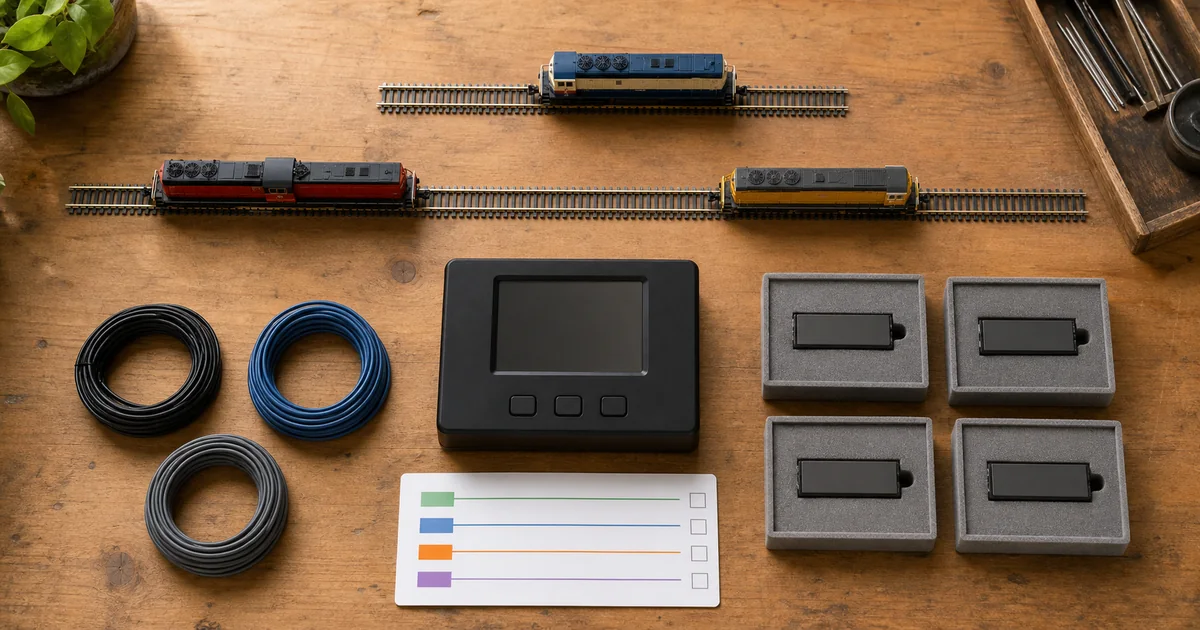
Use the programming-track workflow to preserve changes, the installation guide to verify output wiring, and the consisting guide when functions must respond through a group address.
Four layers that SERP answers often collapse
| Layer | Question it answers | Typical evidence |
|---|---|---|
| Throttle command | Which key or packet state is sent? | Throttle/command-station capability and function label. |
| Decoder action | Which wire, pad, light channel, sound slot or internal action responds? | Exact decoder output diagram and function matrix. |
| Effect logic | Is the output steady, dimmed, flashing, directional or conditional? | Manufacturer-specific lighting/effect CVs or graphical rules. |
| Consist routing | Does the action respond at the locomotive address, consist address or both? | CV21/22 implementation plus command-station behavior. |
What official and first-party sources establish
| Source | Verified point | Boundary |
|---|---|---|
| NMRA S-9.2.2 | Defines shared CV roles including consist function controls and baseline function mapping. | Optional implementation and manufacturer extensions still vary. |
| Digitrax | Publishes a CV33–46 calculator and decoder-specific function-mapping guidance. | Its tables are not proof of another decoder's implementation. |
| TCS | Shows that even within one brand, mapping models and CV values can differ by decoder generation. | A TCS example is not a generic DCC recipe. |
| JMRI DecoderPro | Displays only mappings represented in the chosen decoder definition; unsupported choices may be unavailable. | Software cannot identify a decoder automatically from a guessed roster entry. |
| FRA lighting research | Prototype headlights and auxiliary lights are operational visibility systems with defined physical performance concerns. | Prototype compliance does not define model function keys or CVs. |
Four Go / No-Go gates before writing
1. Identity gate
GO only when locomotive, decoder, firmware if known and matching manual/definition are recorded.
2. Output gate
GO only when the physical output or sound action and its electrical load are known.
3. Baseline gate
GO only when current mapping, effect and consist-routing values are preserved.
4. Test gate
GO only when key, direction, motion, address and unchanged-neighbor states can all be observed.
Exclusive tool 1: bit-mask arithmetic checker
Select weights only after the exact decoder manual identifies them for the target CV. This calculator adds bits; it does not choose the CV, output, page or correct behavior.
Function-mapping fault matrix
| Symptom | Do not assume | Next evidence |
|---|---|---|
| Key does nothing | That the key number is wrong. | Throttle range, decoder support, output wiring, map, effect enable and address. |
| Wrong output responds | That wire colors or pad names transfer between decoders. | Exact output diagram and preserved baseline map. |
| Works solo, not in consist | That mapping was lost. | CV21/22 support, consist address and command-station routing. |
| Direction is wrong | That remapping alone controls direction. | Normal direction, consist orientation and separate effect conditions. |
| Several functions changed | That one CV is isolated. | Bit sum, indexed page, shared rule, decoder definition and rollback values. |
Exclusive tool 2: reversible function-map passport
| Record row | Minimum evidence | Release condition |
|---|---|---|
| Identity | Locomotive, decoder, firmware, manual revision and software definition. | No guessed decoder family. |
| Before map | Key, output/action, mapping value, effect, direction and consist routing. | Every changed field has a rollback value. |
| Target | One plain-language observable behavior and required unchanged outputs. | No ambiguous “make lights work” request. |
| State grid | Off/on, stopped/moving, forward/reverse, solo/consist and adjacent keys. | All required and unchanged states pass. |
| Reopen list | Decoder, firmware, wiring, load, throttle, station, consist or requirement changes. | Any trigger returns to baseline comparison. |
Six steps from identity to rollback proof
1. Identify the exact decoder and output
Record locomotive, decoder model, firmware if known, physical output or sound slot, current function key, direction conditions and every readable baseline value before changing anything.
2. Define one observable behavior
Write one plain-language target such as rear light on F1 only when moving reverse; do not combine key mapping, effect, brightness and consist routing into one unexplained request.
3. Select the supported mapping method
Use the exact decoder manual or matching DecoderPro definition to identify the implemented CVs, indexed pages or graphical mapping workflow; never paste a generic CV33-to-CV46 recipe across decoder families.
4. Preserve and write one change
Save the current values and roster, isolate the intended decoder, then write only the smallest supported mapping change using a programming method appropriate to the equipment.
5. Test the full state grid
Test the chosen key off and on, forward and reverse, stopped and moving, individual and consist address where relevant, plus adjacent keys and outputs that must remain unchanged.
6. Release or roll back
Keep the change only when every required and unchanged state passes; otherwise restore the preserved values, prove the baseline and investigate decoder identity, output wiring, effect logic or consist routing.
Railway-culture answer: lighting communicates state
FRA research evaluates locomotive headlights and auxiliary lights as visibility systems, including how observers identify targets and light patterns. The modeling lesson is limited but valuable: a light is an operating indication, not merely an available output. Define what the modeled state should communicate before assigning a key. Prototype rules and photometric tests do not specify decoder CVs.
Official and first-party sources
Checked 2026-08-27. Always use the exact decoder manual and current software definition.
- NMRA — approved S-9.2.2 configuration variables
- NMRA — documents under revision
- Digitrax — CV calculators and function mapping
- Digitrax — function mapping guidance
- TCS — light function remapping
- JMRI — DecoderPro Function Mapping Pane
- FRA — locomotive LED headlight and auxiliary-light testing
FAQ
What is DCC function mapping?
Function mapping links a throttle function command to a decoder-controlled output or internal action. It is separate from the output's lighting effect, brightness, direction logic and consist-address behavior.
Are CV33 through CV46 universal for every decoder?
No. They have standardized mapping roles, but implementation, available outputs and manufacturer extensions vary. Some decoders use indexed CVs or a proprietary graphical mapper.
What is the difference between a function key and a function output?
The key is the command sent by the throttle, such as F1. The output is the decoder wire, pad, light channel, sound slot or internal action that responds after mapping and logic are applied.
Can one function key control more than one output?
Some decoders permit it, while others limit mapping direction or use different models. Confirm the exact decoder's matrix instead of assuming a universal many-to-many capability.
Can one output respond to more than one key?
That also depends on the decoder's mapping model. A bit matrix may allow combinations, while other firmware uses a one-button field or manufacturer-specific logic.
What do CV21 and CV22 do?
They have standardized roles for deciding which functions may respond through an advanced consist address. They do not replace the locomotive's ordinary output map, and implementation must be checked.
Why did a mapped light stop working in a consist?
The locomotive map may be correct while consist function routing excludes that key, or the throttle may send functions through another address. Test individual and consist addresses separately.
Does DecoderPro make function mapping universal?
No. DecoderPro presents controls from the selected decoder definition and can simplify bit fields, but it cannot add unsupported outputs or guarantee that the wrong decoder definition is safe.
Should I calculate a function-mapping CV by adding bit values?
Only when the exact decoder manual defines that CV as the relevant bit mask. Arithmetic can calculate a sum, but it cannot identify the correct CV, page, output or firmware behavior.
Can function mapping damage an N scale decoder?
A mapping error commonly causes wrong behavior, but output wiring, load, voltage and current remain separate electrical limits. Never use mapping to justify an unverified physical load.
How should I test directional headlights after remapping?
Test the function off and on while stopped, forward and reverse, then repeat under the individual and consist address if applicable. Also prove that every supposedly unchanged output still behaves correctly.
When should a function-map release be reopened?
Reopen it after changing decoder, firmware, wiring, output load, throttle, command station, consist policy, decoder definition or operating requirement, and whenever a mapped or adjacent function behaves differently.